user02, Author at Slewing Ring Bearings Manufacturers Suppliers Exporters - 第13页 共13页


5 1 月, 2022

Crane Slewing Bearing

SLEWING RING SYSTEM CONTINUOUS ROTATION

Turning endlessly. Effer slewing ring system allows the crane to rotate continuously. For the transport of oil and electrical signal from the base to the moveable part, Effer makes use of an innovative and reliable rotary distribution system which does not set limits to the crane’s maneuvers in any way.

EXTERNAL GEAR MOTOR

Push with all your might. The external gear motor does not have dimension problems like the internal gear motor. For a medium sized crane, this solution allows you to use high power motors without any space requirement.

Backlash rules. The external gear motor can adjust the position in relation to the bearing to reduce the bearing/pinion backlash by means of ordinary tools.

crane slewing bearing ALT

BEARING FASTENING

Total attachment. All Effer rotation bearings are fastened by means of high resistance screws tightened with a dynamometric wrench.

Slipping softly. Effer rotation bearing uses two revolutions of ball bearings to reduce to a minimum the rotation friction

RACK AND PINION SYSTEM

MECHANICAL SOLUTIONS TO REDUCE FRICTION

Position of the guides. The lower and upper guides of the crane column are at the widest possible vertical distance to ensure their maximum stability and minimum power loss.

Position of the rack. The position of the rack between the guides decreases the column bending and therefore the friction in relation to the guides.

Opposing thrusts. The rack is located on the opposite side of the crane boom. In this way it opposes the column bending, contributes to the reduction of backlash and reduces the power loss due to the friction between the column and guides.

VARIABILITY OF THE DEAD CENTER

Versatility. The rack system can be adjusted to vary the position of the dead center in the event of a second installation on a new truck.

ROTATION SPEED AND POWER CONTROL SYSTEM

Rotation under control. Effer uses gear motors with various reduction stages. The operator can thereby adjust the crane rotation speed, and check the movement of the load on the hook in an extremely safe and precise manner.

Very fast, very slow. The various reduction stages of the engine RpM result in maximum operating power even at minimum rotation speed.

Strong in every sense. The Effer system ensures constant rotation power in any boom working position in relation to the truck.

LEAK-TIGHT SEALS

Protection from the exterior. Effer cranes’ rotation bearing is equipped with a leak-tight seal between the rotary rings, to prevent water and dust entering in the tracks.

GEARS OF REDUCED DIMENSIONS

More than 360°. Effer rack rotation system has gears of reduced dimensions, given the use of special materials. This allows you to obtain rotation angles wider than average, of more than 360°.

  1. BACKLASH RECOVERY ADJUSTERS

    No more backlash. Effer rack rotation system foresees the use of an adjuster which can reduce the mechanical backlash between column and rack over time.

    GREASING IN ONE POINT

    All together. Effer designed the rack rotation system so that all the base greasing points are close to make maintenance operations easier.

    2.Slewing Ring Bearing condition monitoring to ensure safe crane operation

    There are several vital design components of a crane, including slew ring bearings. These bearings allow the crane to rotate 360 degrees, while sustaining the load of the crane slewing bearing and associated weights, including the payload and counterbalance. A failure of the slew ring bearing would result in an operational breakdown that could end in catastrophe.

    Other potential outcomes of crane failures include increased replacement and maintenance costs for your business. Luckily, there are several ways in which you can assess and prevent potential failures from occurring. One of those methods is condition monitoring.

    WHAT IS CONDITION MONITORING?

    Condition monitoring is a testing method that allows a company to uncover how the specific bearings being tested are performing while the machine is in operation. As a result, potential equipment failures can be detected early on and remedied well in advance. For slew ring bearings, purged grease is analyzed.

    Carefully thought out and documented sampling techniques are a must for condition monitoring to be successful. Inadequate condition monitoring procedures can provide companies with a false sense of security that can land said companies in a dangerous position down the line. Proper sampling of used grease will not only compliment your other monitoring strategies, but also shed light on the actual condition of your bearings.

    First, you’ll want to perform a standard grease analysis. This test with provide insights into the batch consistency of your grease. However, a standard grease analysis will not provide you with the full picture and must be supplemented with additional tests. You will want to also conduct tests that identify the presence of contaminants within the grease samples. Generally, a bearing’s grease will accumulate a variety of materials due to the following factors:

    • General operation
    • Overload
    • Fatigue

    It is recommended that companies test six to eight sampling locations per bearing. The results should then be trended. Your company will be able to see an accurate visual representation of your specific bearing’s performance and pivot if necessary. If deterioration is present, it will be shown through the trend report.

    Visual inspections should be utilized as well. Generally, if you can see a crack or other defect, you’re already in need of a repair, but it’s good to cover your bases regardless. You can never have too much monitoring, especially if it prevents catastrophes from happening.

    Condition monitoring will allow your company to catch potential failures in their infancy. From there, your company will be able to remedy current risks as well as create systems centered around preventing risks from occurring in the first place.

    Do you have a condition monitoring plan for your cranes or other heavy machinery? Tell us about it in the comments.

    Cranes are robust machines with a wide range of motion and high load capabilities. Slew rings play a valuable role in crane operation, which is why durable designs and regular maintenance are vital to a ring’s overall function. At SlewMaster Inc., our slew rings for cranes offer durability from beginning to end. With regular maintenance, our components are a cost-effective solution for any design.

    The Function of a Crane Slewing Bearing

    In lifting equipment like cranes, slew rings create a joint between the undercarriage and the upper structure of the machine. These bearings allow cranes to turn 360 degrees while supporting other diverse movement requirements, from thrust and radial motion to tilting. The crane slewing bearing open design allows hydraulic systems and other control components to pass through the ring for more efficient use of space.

    Slew rings play a critical role in crane operation due to their many responsibilities. While crane slewing rings regulate many movement types, they also withstand the weight of the equipment and its various loads, including payload and counterbalance.

    Crane Slewing Bearing/Crane Slewing Ring Bearing:

    Since cranes are rated at their maximum capable lifting load, it is important to review how far away from the center of the crane this load can be lifted. This is directly related to the crane slew bearing and is referred to as “Tiling Moment Capacity.” A crane may have multiple vital components for its operation, but a slew ring is the most critical component in designing a crane load chart. Overall, the slew ring will reflect how much load a crane can lift, and the allowed distance where this load can be lifted at safe operating conditions.

    Why Is Crane Slewing Bearing Maintenance Important?

    Crane slewing bearings support many of a crane’s functions. If any one of these components fails, the equipment and its operators are at risk. The majority of slew ring failures revolve around overloading, incorrect installation and surface lubrication issues. Among the three problems, lubrication is the most common maintenance mistake.

    Since slewing rings are responsible for various movements and weight balancing, they require high-pressure grease to prevent surface roughening and cracks caused by friction and debris. With enough wear from these factors, slewing rings can spall, leading to complete machine failure.

    Regular lubrication is the solution to early wear in a crane slew ring. During these maintenance checks, individuals should also perform torque checks on bolts to ensure the system is prepared to operate at maximum capacity levels.

    Condition monitoring can also help teams identify system failures as they happen. This type of maintenance check will often require a grease examination to determine the lubricant’s quality and effectiveness in preventing wear.


    Work With LYMC to Maintain Your Crane Slewing Ring

    LYMC Bearing carries a selection of slewing rings for your project applications.  Engineers can meet heavy-load requirements in crane designs. The helical teeth configuration allows for pinion meshing and worm gear meshing in slew drives. Our team works with different applications engineers to assist in selecting the appropriate product for their cranes. Through understanding the final crane load requirements, safety factors and material treatments, we are able to provide standard and custom-made solutions across multiple models.

    We use durable materials and advanced slew ring designs to deliver cost-effective solutions to equipment engineers. We act as a technical consultant for your team to find the right slewing ring configuration for your heavy equipment project.

    Our crane slewing bearings are an excellent addition to a machine in the early design process. Our slew rings for cranes are also a valuable replacement if your existing ring starts to spall. With the proper lubrication and maintenance, our slew rings offer longevity and heavy-load performance.


    Contact Us for Crane Slew Bearing Solutions

    At LYMC Bearing, we partner with your team to deliver in-stock and custom solutions. Our crane slewing bearing offer longevity with the correct care, making them an excellent addition to any machine. Get in touch with us today to learn more about our products.


4 1 月, 2022

Excavator Slewing Bearing

Excavator Slewing Bearing

The excavator slewing bearing device is composed of a turntable, a slewing bearing and a slewing mechanism, the outer ring of the slewing bearing is connect to turntable with high strength bolts (it divides three stages forcing the bolts pre-tightening), inner race with teeth and chassis connected by bolts, inner race and outer race has rolling body, the rolling body usually divided into ball type and column type, according to different working condition to choose.

The vertical load, horizontal load and overturning moment of the excavator device on the turntable passed to the chassis through the outer race, rolling body and inner race. The housing of the rotary mechanism is fixed on the turntable and messed with the gear ring on the inner race of the slewing bearing through the pinion. When you adjust clearance especially important is the first installation, specific details please refer to our clearances technical of slewing bearing information.

The pinion can rotate around its own axis and revolve around the centreline of the turntable. Once the rotary mechanism works, the turntable rotates relative to the chassis. Due to the poor working condition of the excavator, regularly maintain could be added the use life of the excavator to a certain extent.

How does an excavator slew work?

In operation, the slew drive’s axial movement, or motion around its axis, interacts to create radial torque. The action occurs by meshing the grooves of the horizontal screw with the teeth of a perpendicular gear. While turning, the worm gear’s axial movement transfers magnified torque force to the radial gear.

Existing form and working principle of excavator slewing bearing

Excavator slewing bearing is one of the important equipment in modern engineering construction. The excavator can rotate left and right during work, which is inseparable from the credit of the slewing mechanism. It is one of the important components of the hydraulic excavator. The slewing mechanism is connected with the walking device through a slewing support, and the slewing drive device makes the platform rotate relative to the walking device and drives it to rotate around its central axis of rotation. Today, the editor will tell you about the existence and working principle of excavator slewing bearings for everyone to learn and understand.

1. The existence of excavator slewing ring

1) rotary column excavator slewing bearing

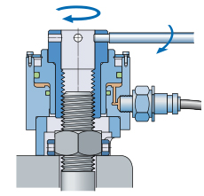
In the structure of the slewing column type slewing bearing, the rotating body and the supporting shaft form a rotating column, which is inserted into the bearing of the bearing seat. The bearing seat is bolted to the frame. The shell of the swing cylinder is also fixed on the frame, and its output shaft is inserted into the lower bearing. The rotating body is driven to rotate relative to the frame. The working device is hinged on the revolving body and revolves with the revolving body, and the rotation angle is not more than 180°.


  1. Rolling bearing type slewing ringexcavator slewing bearing alt


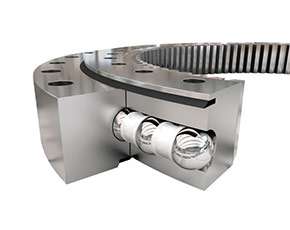
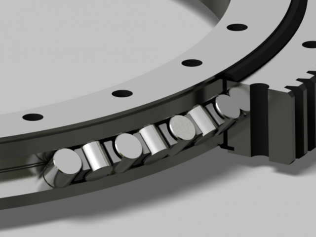
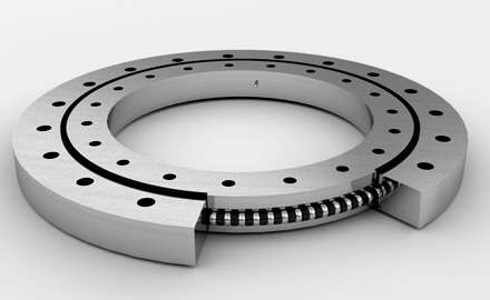
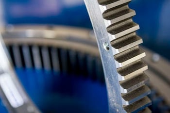
Rolling bearings are compared with ordinary bearings. The speed is very slow, and the commonly used structure has two types: single-row ball and double-row ball. The single-row ball slewing bearing is mainly composed of inner ring, outer ring, isolator, rolling element and upper and lower sealing devices. The steel balls are separated by rolling elements, and the inner ring or outer ring is processed into an inner ring or an outer ring.


The inner gear ring is fixed on the walking frame, and the outer ring is firmly connected with the rotary platform. The slewing drive device is fixedly connected to the slewing platform and generally consists of a slewing hydraulic motor, a planetary reducer, and a slewing drive pinion. Through the meshing transmission of the driving pinion and the ring gear, The rotary device revolves around the inner ring gear while rotating. Thereby driving the platform to rotate 360°.

  1. Working principle of transmission

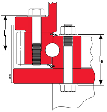
When the excavator slewing bearing is working, the position of the combined force of the upper part of the turntable and the load is constantly changing, and is biased towards the direction of the load. In order to balance the load moment, each device on the turntable needs to be reasonably arranged, and a counterweight is set at the tail to improve the force of the lower structure of the turntable, reduce the wear of the slewing bearing, and ensure the stability of the whole machine.

As the speed increases, the flow rate required by the swing motor also increases. When all the oil of the hydraulic pump is supplied to the swing motor, the start phase ends. The accumulator releases its energy at this moment, so the hydraulic pump and the oil from the accumulator are supplied to the slewing motor together, which speeds up the speed of the slewing motor. This is the second stage of starting.

The above is a brief introduction to the existence form and working principle of the excavator slewing bearing. Here is a reminder that after the excavator is used for a period of time, its slewing bearing is prone to noise, impact and other faults. The operator should pay attention to observe and check in time to eliminate malfunction. Only correct and reasonable maintenance and maintenance of the slewing ring can ensure its normal operation, give full play to its performance and extend its service life.

What is slewing in an excavator?

Slewing refers to rotating the excavator’s house assembly. Unlike a conventional backhoe, the operator can slew the entire house and workgroup upon the undercarriage for spoil placement.

Does slew mean a lot?

The definition of a slew is a large quantity of something. … A large amount or number; a lot. A slew of unpaid bills.

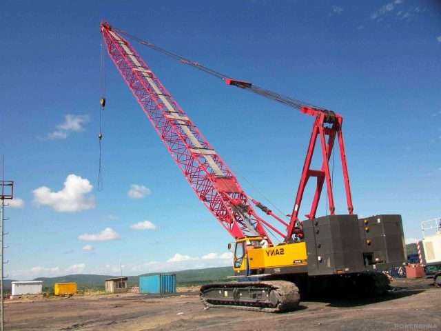
What is the difference between a slewing and non slewing crane?

In crane movement terms, a slewing crane lifts its load, suspends that load in mid-air, and then rotates it via a boom rotating mechanism. Non-slewing cranes, on the other hand, lack a rotating base section.

Is it Slough or Slew?

Slew is an informal word equivalent to many or lots (you have a slew of cattle). It is sometimes misspelled slough (a legitimate noun meaning “a grimy swamp” and pronounced to rhyme with now) or slue (a legitimate verb meaning “to swing around”).

How does an excavator swing brake work?

The discs and plates are lubricated by the release signal oil. When the engine is shut off, the swing brake is engaged by spring pressure on the brake pack. … This pressure signal enters the brake housing and releases the brake by forcing the piston to compress the brake spring.

What is a Rotex bearing?

Rotek slewing bearings are machine elements which absorb all axial and radial forces and the resulting tilting moments in a single self-retaining and ready-to-install unit.

What is a slew bearing on an excavator?

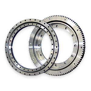
Excavator Slewing bearings comprise an inner ring and an outer ring, one of which usually incorporates a gear. Together with attachment holes in both rings, they enable an optimized power transmission with a simple and quick connection between adjacent machine components.

What slewing means?

transitive verb. 1 : to turn (something, such as a telescope or a ship’s spar) about a fixed point that is usually the axis. 2 : to cause to skid : veer slew a car around a turn. intransitive verb. 1 : to turn, twist, or swing about : pivot.

What is slew radius?

Radius. The horizontal distance from the reference line (e.g. centre of rotation of a slewing crane) to the load line (typically through the crane hook). Regular Load.

What is non-slewing?

A non-slewing mobile crane is a powered mobile crane that incorporates a boom or jib which does not slew and includes an articulated mobile crane or a locomotive crane but does not include vehicle tow trucks.

What does non-slewing mean?

A non-slewing mobile crane means a mobile crane, of greater than three tonnes capacity, incorporating a boom or jib that cannot be slewed. Includes: articulated type mobile cranes.

Is a Franna a slewing crane?

Successfully completing this course will allow you to operate any mobile cranes (up to 20t), any non-slewing crane (such as telehandlers or Franna cranes) and vehicle loading cranes (such as Hiab’s and Palfinger’s) and reach stackers within Australia.

LYMC excavator slewing bearing supplies the slewing rings to a wide range of the excavators, a good replacement slewing ring bearings used on Komatsu, Hitachi, Kobelco, Caterpillar, Hyundai and so on, we can supply according to the most of the machine number, and a lot of slewing rings are in stock for the quick delivery.
Below is the normal machine number we can supply the slewing ring bearings.The list of Crane and excavator.

For more types,please contact us freely.


2 1 月, 2022

Slewing Ring Bearing

Slewing Ring Bearing

slewing-ring-bearing
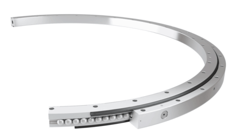
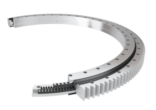
Slewing ring bearings, or turntable bearings, are ball or roller style bearings composed of two concentric rings either of which may include a gear. This type of bearing enhances load support and power transmission in all directions, and is typically employed to support heavy loads for slow applications and large equipment such as earth excavators and construction cranes. The unique power and versatility of slewing ring bearings has made them increasingly valuable in a wide array of industries, including construction, industrial, robotics, machine tooling, and medical applications.

Slewing Ring Bearing Types

LYMC Bearing is pleased to offer slewing ring bearings from high-end brands, including Rothe Erde® (Rotek), Silver Thin™, and Scheerer Bearing Corporation. Depending on your application needs, these bearings are available in a variety of designs.

Series 1000 Single Row Ball Slewing Ring

The Series 1000 is a gearless-only bearing model composed of chrome-alloy steel balls without spacers in unhardened raceways within steel rings.

Series 2100 Single Row Ball Slewing Ring

The Series 2100’s single-row design offers four-point contact in induction-hardened, offset raceways.

Series 3000 Single Row Ball Slewing Ring

The Series 3000 is an adaptation of the four-point contact slewing ring constructed with offset hardened raceways, quality raceway wrap, and sturdy ball separators.

Series 4000 Two Row Ball Slewing Ring

Series 4000 is built with greater internal clearance than the series 3000 model for enhanced mobility.

Series 5000 Cross Roller Slewing Ring

The Series 5000 Cross Roller is built V-groove style raceways, to provide two paths for rollers in each ring.

Series 6000 High Speed Slewing Ring

Our single row Series 6000 is a high-speed radial ball slewing ring that can provide raceway velocities up to 3,000 feet per minute with sufficient lubrication.

Series 7100 Vertical Thrust Slewing Ring

Series 7100 Vertical Thrust Slewing Rings are a single-row ball bearing specifically designed to support applications in which the center of force stays inside the diameter of the slewing ring during standard operation.

Series 8000 Vertical Thrust Slewing Ring

Similar to the 7100, the 8000 is a single-row ball bearing that supports vertical movement within the slewing ring’s diameter. The 8000 model offers the lowest cost per unit diameter for heavy, pure-thrust loads.

Series 10,000 Three Row Roller Slewing Ring

The series 10,000 is built with three rows of rollers that move independently for optimal support and freedom of movement in the desired direction.

Series 12,000 Roller and Ball Combination Slewing Ring

The Series 12,000 combines both rollers and balls to account for small movement eccentricities at relatively high axial loads for enhanced load support and stability.

Series 15,000 Wire-Race™ Slewing Ring

Our Series 15,000 Wire-Race™ Slewing Ring includes a replaceable hardened wire raceway, which allows the supporting rings to be created using a wider assortment of materials.

Precision Slewing Rings

LYMC’s precision slewing rings are designed to facilitate highly accurate support and mobility to exacting specifications, including:

  • Run-out tolerances within .0003”
  • Concentricity within .0003”
  • Surface flatness within .0003”
  • Parallelism within .0003”
  • Bolt hole positions .010” diameter
  • Gear precision equals or exceeds AGMA 10 standards

Slewing Ring Bearing Applications

Slewing ring bearings are often relied upon to support loads in very large, heavy-duty equipment. Their exceptional combination of heavy load support and mobility enhancement makes them useful in a variety of industries and applications, including:

  • Fifth Wheels on Trailers and Farm Vehicles
  • Cranes
  • Excavators
  • Stackers and Reclaimersslewing-ring-bearings
  • Lift Truck Rotators
  • Turnstiles
  • Mining Equipment
  • Machining Tools
  • Radar Antennas
  • Tunnel-Borers
  • Log Debarkers
  • Coil Winders
  • Pay-Off Reels
  • High-Speed Capstans
  • Large, Precision, and Index Turntables
  • Water Treatment Facilities
  • Clarifiers, Thickeners, and Rotary Distributors
  • Mooring Buoys
  • Robotics Equipment
  • Medical Diagnostic Equipment
  • Bottling Equipment

Slewing Ring Bearings From LYMC Bearing

For more than 50 years, LYMC Bearing has been the go-to provider of top-quality roller and ball bearings for customers around the world. Our selection includes everything from miniature precision bearings to five-foot mill bearings in a variety of styles and materials to suit the needs of your applications. We are dedicated to providing our customers with the right bearings at competitive prices. We offer a wide range of services, including:

  • One-Stop Shopping Experience
  • Extensive Inventory
  • Worldwide Sourcing Network
  • Bearing Troubleshooting Capabilities
  • Online Product Catalog
  • Comprehensive Online Reference Tool
  • Same-Day Shipping
  • Fixed Price Program
  • Guaranteed Customer Support 24/7
  • OEM and MRO Expertise
  • OEM Parts Interchange Services

LYMC provides personalized and professional service to our customers worldwide. To learn more about LYMC’s top-of-the-line bearing products and solutions, contact us today or request a quote!

SLEWING RING BEARINGS – COMPONENTS(TURNTABLE BEARINGS)

  • Inner Ring and Outer Ring
  • Rolling Elements
  • Spacers, Spacer Balls & Separators
  • Mounting Holes
  • Seals
  • Load Plug
  • Taper Pin
  • Gear
  • Grease Fitting
  • Part Numbers

Drawing showing the components of a slewing ring

Inner Ring and Outer Ring

Slewing ring bearings are comprised of two rings, each of which contains a precision raceway that is induction hardened on the surface to a specified depth. Each ring is made from a medium carbon steel forging. Silverthin™ SK and ST Series bearings have raceways constructed in a four-point contact configuration, with 45° contact angles as standard. Other raceway configurations are available, such as crossed roller and eight-point contact. These other options are often considered in cases where very high loads or special stiffness requirements are needed.

Rolling Elements

Precision rolling elements (specifically hardened chrome alloy steel balls for Silverthin™ SK and ST Series bearings) facilitate relative ring rotation between the inner and outer rings. Rollers as rolling elements are also often used.

Spacers, Spacer Balls & Separators

Spacers, typically made from a plastic material, are commonly used to separate balls to prevent them from rubbing directly against each other. Sometimes spacer balls are utilized instead of spacers. In this case these are balls that are slightly smaller than the load carrying balls, placed between each load carrying ball. Occasionally, application parameters warrant the use of a separator.

Mounting Holes

Mounting holes are generally spaced around the faces of the inner and outer ring along a uniform bolt circle and equal spacing. These holes can be thru holes, tapped holes, blind tapped holes, counter-bored holes, etc. Sometimes bolt circle or spacing requirements need to be customized to meet the demands of a specific application, in which case custom options are available. In the case of either the standard part numbers listed in this catalog, or other custom versions provided by Silverthin™, the equipment designer, manufacturer, or user is responsible to determine that the mounting design is adequate.

Seals

Seals are provided on each side of the bearing, with their primary functions being grease retention and prevention of some contamination such as dust and debris from entering the bearing. The seals are typically made from an extruded Buna-N rubber strip, and in smaller sizes are a metallic non-contact shield.

Load Plug

Due to the nature of the race hardening process, there is a gap in the race hardness of each race. In that location for the non-geared ring, or the outer ring for ungeared bearings, a hole is drilled to permit the loading of balls into the final slewing ring assembly. This hole is plugged and secured with a taper pin. Note that for the ring where a load plug is not present, an ‘S’ is stamped on the face of that ring at the location of the unhardened gap in the race (also known as the soft spot). Removal of the load plug voids the warranty.

Taper Pin

Secures load plug to the inner or outer ring.

Gear

Slewing ring bearings can be supplied as ungeared, or with gears on either the ID of the inner ring or the OD of the outer ring. Gears are typically a standard stub involute spur gear with backlash provisions and AGMA Q8 quality minimum. Details for each bearing can be found in the enclosed dimensional tables, and drawings are available from Silverthin™ Engineering. Custom gear configurations are also available.

Grease Fitting

At least one grease fitting is included in one of the rings. The quantity may increase with the diameter of the bearing. For bearings with gears, the grease fitting(s) are located on either the ID or OD of the ungeared ring. For ungeared bearings, Silverthin™ ST Series and SK Series slewing rings come equipped to accommodate grease fittings on either the inner or outer ring. Custom quantities, locations and configurations for grease fittings are available.

Part Numbers

Part numbers and serial numbers are etched on one of the faces of the bearing.

SLEW / TURNTABLE BEARINGS

Slew & Turntable Bearings

  • Bore diameter starting from 50 mm
  • Simple installation
  • Available in various, individual versions 
  • Available with internal or external gear and without gear
  • Corrosion-resistant types available on short notice
  • Generally short delivery times

Turntable bearings – For heavy-duty applications

The rugged ball-bearing slewing rings from Isotech are characterized by their large diameter and large bores with only a small cross-section. They were designed for axial, radial as well as combined axial and radial loads. New design concepts and improved manufacturing processes for the ball-bearing slewing rings, enable our customer’s designers to implement completely new solution approaches. The bearings are very easy to assemble and demonstrate their properties particularly in small, sophisticated and high precision applications such as in the aerospace industry or in the special machinery area.

The bore diameter of the Isotech ball-bearing slewing rings is at least 50 millimeters. The bearings are available with and without gear teeth, optionally in a corrosion-resistant or a customer specific tailor-made design.

Features and benefits of the turntable bearings

  • Bore diameter starting from 50 mm
  • Simple installation
  • Available in various, individual versions
  • Available with internal or external gear and without gear
  • Corrosion-resistant types available on short notice
  • Generally short delivery times


31 12 月, 2021

Crossed Roller Bearings

Crossed Roller Bearings

Crossed-roller bearings are bearings for high-precision applications whose dimensions conform to ISO dimension series 18 as per DIN 616. They comprise outer rings, inner rings, rolling elements and plastic spacers. The outer ring is split and is held together by three retaining rings.

Due to the X arrangement of the cylindrical rollers, these bearings can support axial forces from both directions as well as radial forces, tilting moment loads and any combination of loads by means of a single bearing position. As a result, designs involving two bearing positions can be reduced to a single bearing position.

Crossed roller bearings are very rigid, have high running accuracy and are supplied with normal clearance, low clearance or preload. The bearing outer rings are easily fixed to the adjacent construction using clamping rings.

The Basis of crossed roller bearings

Crossed roller bearings provide more accuracy, rigidity, and weight-bearing capacity for linear motion than other commonly used friction-reducing devices such as ball bearings. And unlike ball bearings, they can support moment loads, radial forces or tilting loads. This lets one crossed roller bearing replace more than one ball bearing, thus saving the space required by ball bearings, lowering the associated material costs.

Crossed roller bearings are preferred for high-precision linear-motion applications with relatively short linear movements that require smooth motion. They are also durable, lasting 150 million cycles, even for linear-motion applications with high levels of acceleration and deceleration when using 2 to 12-mm rollers and 30 to 600-mm lengths.

They can be found in medical and lab equipment, machine tools, semiconductor processing, clean rooms, vacuum environments, material handling, and automation machinery. And as technology becomes more demanding, requiring greater and greater precision, crossed roller bearings will also become more common.

Crossed Roller Bearing Basics

A crossed roller bearing, also called a crossed roller slideway, is effectively two sets of
bearings and races combined at right angles to each other. Cylindrical bearings or rollers mount along the length of a rail in a carriage. The rollers are held in place with a cage, preventing roller-to-roller contact, which increases friction and wear. Keeping rollers separated also eliminates any risk of them jamming.

If you were to number the cylindrical rollers along the rail, the even ones would be mounted at 90° to the odd ones. In other words, the rollers alternate orientation. This lets the line of alternating rollers support loads from all directions, including high overturning moments, and because they do not recirculate like some ball bearings that line linear rails, all the rollers are constantly carrying the load except for pure radial loads, where, due to the criss-cross arrangement, only half of the rollers take loads at any one time.

The cylindrical rollers are mounted such that they create a protruding V-shape on the sliding rail. It fits into a corresponding V notch in the other rail that is likely carrying
the load.

crossed roller bearing

Rollers provide a full line of contact rather than just the point of contact a ball bearing provides. This gives crossed roller bearing a broader contact surface and the ability to carry heavier loads. It also increases the bearing’s rigidity so it deforms less and is thus more accurate. Plus, erosion is slower due to the crossed rollers’ consistency of contact between the carriage and the base.

There is a direct correlation between the combined contact area of all the rollers and load capacity: the greater the area, the higher the capacity. This lets bearing designers adjust load capacity by up to 250% by mounting rollers closer together. This permits more rollers to fit in the same space and increases the amount of weight per inch the bearing can carry.

Cross roller bearing do not use seals due to their construction, high precision, and low friction. Still, it is important to keep contaminants away from the rollers to prevent damage and wear. One way this is done, especially in IC manufacturing and lab equipment, is to install the machines using crossed roller bearings in clean, contamination-free environments.

It is also important to lubricate crossed roller bearings to get the most operational life out of them. A standard lubricant for them is lithium-soap-based #00 grease.

The configuration of crossed roller bearings gives designers all the benefits of a two-row bearing, including stability, in a single-row space.

Accuracy and Rails

Because of crossed rollers large contact area, they deform less than recirculating ball bearings and are stiffer, creating more precise and consistent motion. Because of this greater stiffness, crossed rollers provide consistently precise movement.

Crossed rollers are less forgiving of mounting surface inaccuracies than recirculating ball bearings due to their rigidity and the way they are designed. Ball bearings can handle imperfections on the order of five to ten 10 microns while crossed roller bearings need imperfections smaller than two microns for ultra precision.

Metal and Plastic Cages

One factor that determines how close rollers can be to each other is the cage (or retainer) holding them all in place, so its design is critical. An important factor in the design of the cage is whether it is made of metal or plastic.

Traditional metal cages use tabs on the carriage that fit into notches on the top and bottom of the rollers to keep them in place. This limits how closely a roller can be positioned between neighboring rollers, which then limits the crossed roller bearing’s load-carrying capacity.

But metal cages are less expensive and can be plain or stainless steel. Metal is more compatible with working in vacuums, including outer space, because plastic can out-gas and cause problems with electronics and optics. Stainless steel can also be beneficial in high-temperate applications and those requiring washdowns and where rust is unacceptable.

Plastic cages fit smoothly around each roller, exposing more of it to the load than a metal cage can. Plastic cages also pack rollers closer together so more rollers can be housed in the same rail. These two features mean the cage and rollers can be shorter while maintaining the same load capacity or the number of rollers can be increased within the same cage (compared to a metal version) and thus increase the load capacity. In fact, a plastic cage can yield a 30% to 58% increase in contact area compared to a metal cage. This increase translates to a 250% increase in load capacity.

Recent development in plastic cages has increased the number of design options available to engineers. They can now be shaped so that there’s even a larger contact area with less space between rollers. Plastic cages can also be thinner in critical areas.

Preventing Cage Creep

Metal and plastic cages both effectively float between the bearing’s rails and they both tend to drift away from the bearing’s longitudinal center over time, a phenomenon called cage creep. It happens when the linear bearing only makes partial strokes, especially when mounted vertically. The cage can restrict slide travel because once the cage has moved and the bearing makes its next full stroke, the off-center cage hits a rail endstop and is forced to center itself by skidding.

Hitting the endstop and skidding can damage the retainer, rollers, and slideway. And it could require a more powerful and expensive motor to offset the effects of creep. Cage creep also means the rollers are not rolling but slipping and causing metal-to-metal rubbing, which leads to wear.

If a crossed roller bearing has no defense against creep, technicians will often have to regularly readjust the linearmotion equipment and replace worn components. Creep
is particularly bad when applications require high levels of acceleration and deceleration, uneven preloading or load distribution, or vertical or inclined strokes.

Fortunately, there are anti-creep mechanisms that stop retainers from slipping by holding the rollers between the two V-grooved slideway rails. As a result, the rails can be used in any mounting orientation, and lower-momentum motors such as linear motors can be used to move the loads. Anti-creep devices also reduce downtime and the cost of maintenance.

One anti-creep device, a rack-and-pinion mechanism, consists of external plastic gears and a metal gear inside the rail. Though effective, this approach is costly and makes it impossible to change out failed or worn bearing components.

Another approach to preventing creep uses rollers with spherical studs circling the middle of the roller’s round surface. As the rollers turn in the rail, they mesh with a row of holes or dimples machined down the exact center of the raceway tracks. This design, called Studroller at NB, prevents slipping regardless of the rail’s orientation or position. It creates smoother tracking motion than gear-based anti-creep mechanisms, so it is quieter and more accurate. Keeping the rollers aligned along the center of the rail also keeps all components aligned.

With the Studroller approach, the number of effective rollers increases by 20% to 55%. Contact area between rollers and the raceway surface jumps by 42% to 58%, which lets the load rating increase by 140% to 230%. This should lead to savings in cost and space required to mount the linear bearing.

Costs vary for crossed roller bearings with anti-creep devices depending on the complexity of the device whether the application must be custom designed and manufactured to accommodate them. The Studroller approach, being the simplest non-slip design, is priced the same as a standard crossed roller slideway, which is roughly half the cost of other anti-creep devices. And there are no redesign costs to replace a standard slideway.

Travel Lengths

For crossed roller bearings on linear sliderails, the rails’ lengths determine the length of the stroke or travel. The entire rail assembly must be twice as long as the stroke. That’s because both rails containing crossed roller bearings move in opposite directions. That means the whole assembly has to have room to move inside a space twice as long as the travel length. (Recirculating-ball bushings used for linear motion need shafts only as long as the required travel because the only moving component is the bushing.)

When the bearing uses plastic cages, stroke length can be longer on a given length of rail because the cage can be shorter for a given load.

So one limit on a crossed roller bearing’s travel is the space available in the application. As mentioned, with the rails moving in opposition to each other, the overall space required is twice the distance the load will travel. Endstops are components mounted on linear rails that physically limit travel length, stopping the rails from going farther.

Ratings and Life

The dynamic load ratings of crossed rolling bearings are based on the industry standard of 50 km of travel. In effect, it means that when you purchase several crossed bearings, 90% of them will last at least 50 km under normal operating conditions at its rated load. Using bearings with load ratings higher than an application requires usually lets the bearing last longer or withstand more demanding conditions.

It’s also important to select bearings with a margin of extra load capacity if accuracy is paramount. That’s because rollers and rails can deform when nearing their load limits, which can change the accuracy, sometimes permanently.


30 12 月, 2021

Slewing Bearing Clearance Measurement

Slewing Bearing Clearance Measurement:

The clearance of the slewing ring bearing is the maximum amount of movement in which one ferrule is fixed and the other rim is radially or axially.

The maximum amount of motion in the radial direction is called the radial clearance, and the maximum amount of motion in the axial direction is called the axial clearance.

The larger the radial clearance, the larger the axial clearance.

The slewing ring bearing clearance can be divided into the following three types:

Original clearance

The slewing bearing clearance in the free state before the bearing is installed. The slewing bearing original clearance is determined by the processing and assembly of the manufacturer.

Installation clearance

Also called the fit clearance is the clearance when the bearing and the shaft and the bearing housing are installed and not working. The installation clearance is smaller than the original clearance due to the interference installation, or the increase of the inner ring, or the reduction of the outer ring, or both.

Work clearance

When the bearing is in working condition, the inner ring temperature rises the most, the thermal expansion is maximum, and the bearing clearance is reduced. At the same time, due to the load, the rolling element and the raceway are elastically deformed, which makes the bearing clearance increase. Big. Whether the bearing working clearance is larger or smaller than the installation clearance depends on the combined effect of these two factors.

The clearance of the slewing ring bearing

Repeat the tilting clearance or axial reduction measurements under the same conditions at appropriate intervals, after first checking the bearing fastening bolts.

Double-row ball bearing slewing rings clearance:

Track diameter Ball diameter mm
up to mm 18 20 22 25 30 35 40 45 50 60 70
permissible increase in bearing clearance mm
1000 1.8 1.8 1.9 1.9 2 2.1 2.5 2.8
1250 1.9 1.9 2 2 2.1 2.2 2.6 2.9 3.4 3.6
1500 2 2.1 2.1 2.2 2.3 2.7 3 3.5 3.7
1750 2.2 2.2 2.3 2.4 2.8 3.1 3.6 3.8 4
2000 2.3 2.4 2.5 2.9 3.2 3.7 3.9 4.1
2250 2.5 2.6 3 3.3 3.8 4 4.2
2500 2.7 3.1 3.4 3.9 4.1 4.3
2750 2.8 3.2 3.5 4 4.2 4.4
3000 3.3 3.6 4.1 4.3 4.5
3250 3.4 3.7 4.2 4.4 4.6
3500 3.5 3.8 4.3 4.5 4.7
3750 3.6 3.9 4.4 4.6 4.8
4000 4 4.5 4.7 5
4500 4.2 4.7 4.9 5.2
5000 4.9 5.1 5.4
5500 5.1 5.3 5.5
6000 5.3 5.5 5.7
6500 5.7 5.9
7000 5.9 6.1
7500 6.3
8000 6.5

Single-row ball bearings (4-point bearings) double four-point contact bearings clearance:

Track diameter Ball diameter mm
up to mm 20 22 25 30 35 40 45 50 60 70
permissible increase in bearing clearance mm
1000 1.4 1.4 1.4 1.5 1.7 2 2.1 2.5
1250 1.5 1.5 1.6 1.7 2 2.2 2.6 2.7
1500 1.6 1.7 1.7 2 2.3 2.6 2.8
1750 1.7 1.8 2 2.3 2.7 2.9 3
2000 1.8 1.9 2 2.4 2.8 2.9 3.1
2250 2 2 2.5 2.9 3 3.2
2500 2 2 2.6 2.9 3.1 3.2
2750 2 2.6 3 3.2 3.3
3000 3 2.7 3.1 3.2 3.4
3250 3 2.8 3.2 3.3 3.5
3500 2.9 3.2 3.4 3.5
3750 3 3.3 3.5 3.6
4000 3.3 3.6 3.7
4500 3.5 3.8 3.9
5000 3.7 4 4.1
5500 3.9 4.2 4.3
6000 4.1 4.5 4.6
6500 4.6 4.7
7000 4.8 4.9
5.1
8000 5.3

Roller bearing slewing rings

The inspection method for the axial clearance of the slewing bearing crane is as follows:

1. Feeling method

Check the axial clearance of the rolling bearing with your fingers. This method is applied to the case where the shaft end is exposed. When the shaft end is closed or cannot be checked with a finger for other reasons, it can be checked whether the shaft is flexible or not.

2,slewing bearing clearance measurement method

measurement method

(1) Check with a feeler gauge. The method of operation is the same as that for checking the radial clearance with a feeler gauge, but the axial clearance should be

c=λ/(2sinβ)

Where c – axial clearance, mm;

Λ——the thickness of the feeler gauge, mm;

Β——bearing cone angle, (°).

(2) Check with a dial gauge. When the shaft is tilted with the crowbar to make the shaft at two extreme positions, the difference between the dial gauge readings is the axial clearance of the bearing.

However, the force applied to the crowbar should not be too large, otherwise the shell will be elastically deformed, and even if the deformation is small, the accuracy of the measured axial play is affected.

Certificate for Slewing Rings clearance Application: Location:
RE drawing-no.: RE-order-no.: Year of manufacture:
Date
Repeated measurements (every 12 months)
Measuring point Basic measurement 1 2 3 4 5 6 7
1 Boom
180offset
2 Boom
180offset
3 Boom
180offset
4 Boom
180offset
Grease-sample no Fe-magn. particle (%) 1
2
3
4
5
6
Greasing system Quantity/interval
Remarks

Given conclusive assessment of the crane slew ring ‘s condition, worn parts can be replaced in good time. In conjunction with optimum spare parts management, it is thus possible to avoid incidents of damage and lengthy downtimes.

  • Measurement of axial clearance for slewing bearing

First, the connecting screw of double half rings in slewing bearing should be tightened uniformly, to ensure the uniform fitting. Then place a datum level of the slewing bearing on the large platform, Three adjustable bearings are equidistantplaced from the neutral position of the lower two steps. Three measuring frame are equidistant placed on the end face of the upper slewing ring, put the pointer on the end face of the other slewing ring. When measuring, first push the three pointer to zero, adjust the bearing, make the slewing bearing face away from the large platform, the average of three pointer is the axial clearance of the slewing bearing.

  • Measurement of radial clearance for slewing bearing

Place the slewing bearing on the platform vertically, lift a slewing ring, Measure the clearance with the dead weight of the other slewing ring, Measure three point along the circumference of 120° and take the average .Other measurements are allowed.


24 12 月, 2021

Slew Bearings,Slew Rings-LYMC Slewing Bearing Manufacturer

Slewing Bearing Assembly:

Slewing bearing is a kind of large bearing with special structure, which can bear the overall load such as axial load, radial load and overturning load.

It combines support, rotation, transmission, fixation, sealing, anticorrosion and other functions into one unit.

  • Inner and outer rings

Generally, slewing bearings consist of two rings, each ring contains  a precision raceway that is Induction quenched on the surface to a specified depth.

Each ring is forged from 50Mn or 42CrMo.

Different internal structures can be selected according to load capacity, including Single-row ball series、Double-row ball series、Double-line ball series 、Roller and ball combination series、Three-row roller series.

  • Rolling body

The precision rolling body can promote the relative rotation between the inner and outer rings.

Steel balls or rollers are often used as rolling body.

  • Isolation block

Spacer blocks usually made of nylon which are usually used to separate balls or rollers,

this prevent them from rubbing against each other directly .

Under special conditions , steel and copper holder can be used.

  • Mounting holes

The mounting holes are usually spaced along the surface of the inner and outer rings which along a uniform bolt circumference and equally spaced apart.

These holes can be through holes, threaded holes, blind holes, countersunk holes, etc. Sometimes, need to customize bolts with spacing requirements to meet a specific application.

  • Sealing strip

There are sealing strips on each side of the slewing ring bearing.

Its main function is to retain grease and prevent certain contaminants (such as dust and debris) from entering.

The seal is usually made of Nitrile Butadiene Rubber.

  • Plug

Drill a hole in the position of the non-gear ring or the outer ring of the non-gear bearing, and install the ball or roller into the slewing ring raceway.

The hole is plugged and fixed with a taper pin.

The unhardened clearance will be engraved with the word “S”, Namely: soft belt.

Slewing bearings are available in toothless or internal or external type.

Custom gear configurations are also available.

  • Greaser

The slewing bearing include at least one grease fitting

The number may increase with the diameter of the slewing bearings.

For gear bearings, the grease fitting is located on the inner or outer circle of the toothless ring.

  • The sign

The part number and serial number are engraved next to the plug of the slewing bearing.

How mounting can optimize slewing ring bearing performance

Mounting a slewing ring bearing in the proper structure is crucial to properly distributing bearing load and stress. Without an adequate structure, bearing performance is likely to suffer. So can the performance of the seals, pinions, gears, and bolts. Therefore, mounting should be considered very early in the design process.

Factors in bearing selection

The designer’s first task, of course, is to specify a size for the slewing bearing. The bearing manufacturer can recommend a size based on applied load and ideal mounting. In heavy equipment, for example, the primary task of the slewing bearing and its mounting structure is to handle an over-turning moment load. Also, a slewing ring bearing with integral gearing must be sized for adequate gear strength and pinion drive position. Another factor is how large the central opening in the bearing bore should be…this may have as much influence on bearing size as the maximum applied load.

Shrouding is another consideration. While most slewing bearings are sealed by their manufacturer, shrouding is usually advisable to help avoid seal damage and dirt and water influx. This is even more important if the application involves cleaning with high-pressure water. Figure 1 shows a typical arrangement.

Kaydon Bearings - mounting slewing ring bearings - typical mounting support shroudThis typical mounting support has a shroud to help keep out contamination.

Mounting structure integrity

The need for rigidity in the mounting structure cannot be over-emphasized. Experienced designers know they should avoid the shortcut of using a higher-capacity bearing to offset a flimsy mounting surface. If the bearing structure is not robust enough to uniformly transfer the increased loads to the bearing while uniformly supporting the bearing, more bearing capacity will not make up for it. The consequences may be clear immediately, as excess deflection or rotational resistance. Sometimes they show up later, as uneven gear wear or reduced performance due to concentrated load.

In many cases designers can follow the bearing manufacturer’s recommended thickness for a steel mounting plate. Such recommendations are based on the size of the rolling elements or ring sections. Thinner plates reinforced with gussets or channels are an alternative (Figure 2), so long as the reinforcement is uniform and has been verified with testing. The use of thin “riser plates” under the bearing should be avoided. They tend to provide rigid support only in localized areas, putting more stress on retaining bolts and rolling elements.

Kaydon Bearings - mounting slewing ring bearings - gussets near bearing mounting holes increase rigidityGussets added near bearing mounting holes increase rigidity.

Mounting structure deflection is another important factor. Finite Element Analysis (FEA) is a good way to evaluate this, but the results should be confirmed with testing (e.g., with a dial indicator), to be sure they are within the bearing manufacturer’s limits. Bearing distortion during maximum loading should be tested as well. Typical allowable mounting-structure deflections for four-point and eight-point bearings, as a function of bearing pitch and ball diameter, are shown in Figure 3. Consult the bearing manufacturer for alternate designs.

Kaydon Bearings - mounting slewing ring bearings - allowable deflection vs. raceway diameterAllowable deflection varies with ball size.

The mounting surface, like the bearing, should be manufactured to precise specifications. Slewing ring bearings mounted on out-of-flat surfaces can produce stress concentrations on the rolling elements even before external load is applied. The bearings are typically assembled at the factory with a small amount of internal clearance that compensates for a little out-of-flatness in the mounting surface.

Figure 4 shows typical allowable mounting surface out-of-flatness for four-point and eight-point bearings as a function of bearing pitch diameter and ball diameter. Consult the bearing manufacturer for alternate designs. Flatness outside the manufacturer’s specifications causes high frictional torque and reduces bearing life accordingly.

Kaydon Bearings - mounting slewing ring bearings - allowable flatness vs. raceway diameterOut-of-flatness, like distortion, should be gradual.

Fastening the bearing

The final step in the interface of bearing and structure is mounting the bearing. It should go without saying that the position tolerance of the mounting holes in the structure must correlate with the holes in the bearing rings and their position tolerance. Most through-holes in construction equipment are drilled marginally larger than the bolt, then true-positioned for proper alignment. Pilot diameters on the inner ring or the outer ring can be useful to locate the bearing and improve gear mesh accuracy.

A full circle of bolts on both the inner and outer rings is the best way to fasten a slewing bearing. Generally, the bolts should be SAE J429 Grade 8 or ISO 898-1, Class 10.9. The hole pattern in the bearing will be appropriate for its load ratings, assuming that the proper mounting and structural support guidelines are followed. However, since variations in mounting structures can affect bolt-load distribution significantly, designers should always verify that the bolts are adequate for their specific applications.

Non-uniform loads not only result in higher-than-desired bolt load, but can leave some areas of the bearing inadequately supported and restrained. This causes poor rolling element load distribution, increasing stress and hampering bearing performance.

All bolts should be tightened in accordance with the equipment designer’s instructions, to minimize the potential for premature wear, equipment damage, and even injury. Bolt tensioning should be done in three stages—30%, 80% and 100% of the equipment designer’s final design tension—using the “star” technique of cross-tightening bolts (see Figure 5). Check bolt tension regularly.

LYMC Bearings - mounting slewing ring bearings - cross-tightening bolts is a proven way to achieve recommended torqueCross-tightening bolts is a proven way to achieve recommended torque.

All bolts should be accurately tightened with calibrated equipment. Two common examples are a torque wrench or a hydraulic bolt tensioner to avoid over-torquing. The Hydrocam bolt tensioner from LYMC (Figure 6), for example, was designed specifically to install the bolts on slewing bearings. It assures uniform preload on all the bolts, optimizes yield strength, and is available in four different designs.

Kaydon Bearings - mounting slewing ring bearings - the Hydrocam hydraulic tensioner from SKF tightens bolts uniformly, without torqueThe Hydrocam hydraulic tensioner from SKF tightens bolts uniformly, without torque.

Bolted joints are made more resistant to loosening by increasing the “stretched” portion of the fastener; that is, the length of bolt from beneath the bolt or screw head to the first thread of engagement, as shown in the inner ring of Figure 7. Additional stretch length may be gained by tapping the mounting hole toward the bottom of the hole.

Kaydon Bearings - mounting slewing ring bearings - stretched bolts resist loosening during thermal distortion“Stretched” bolts resist loosening during thermal distortion.

Conclusion

Mounting structures play a key role in the performance of slewing ring bearings and should be considered early in the design process. A properly-sized bearing, mounted on a flat, rigid surface with the appropriate deflection and fastening strength, should readily achieve its full capacity and contribute to a successful application.


About us

Headquarters

Luoyang MC Bearing Technology Co.,Ltd (LYMC)
+86 13837949030

www.chinaslewingbearings.com/

[email protected]

LOCATIONS

We are everywhere


GET IN TOUCH

Follow our activity

LYMC bearings are the perfect alternative to the most common and well-known brands.