Blog - 第15页 共15页 - Slewing Ring Bearings Manufacturers Suppliers Exporters


31 12 月, 2021

Crossed Roller Bearings

Crossed Roller Bearings

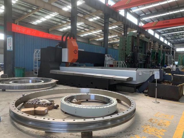
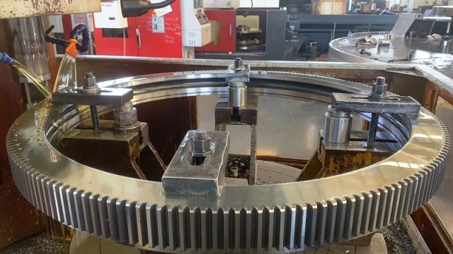
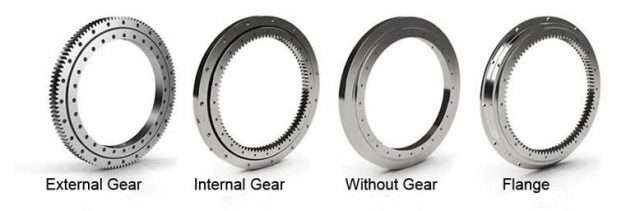
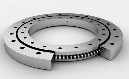
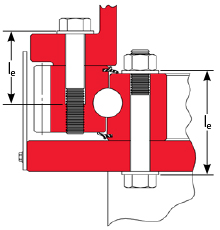
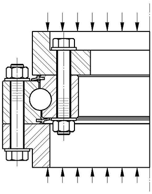
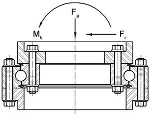
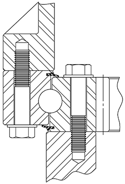
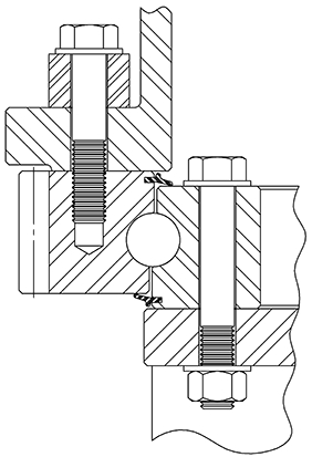
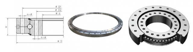
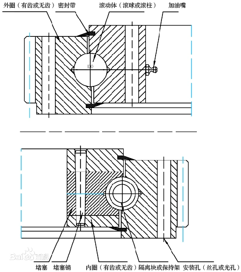
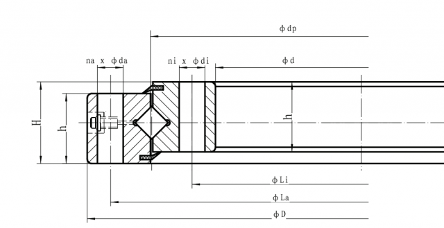
Crossed-roller bearings are bearings for high-precision applications whose dimensions conform to ISO dimension series 18 as per DIN 616. They comprise outer rings, inner rings, rolling elements and plastic spacers. The outer ring is split and is held together by three retaining rings.

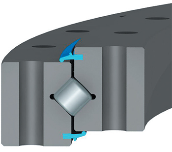
Due to the X arrangement of the cylindrical rollers, these bearings can support axial forces from both directions as well as radial forces, tilting moment loads and any combination of loads by means of a single bearing position. As a result, designs involving two bearing positions can be reduced to a single bearing position.

Crossed roller bearings are very rigid, have high running accuracy and are supplied with normal clearance, low clearance or preload. The bearing outer rings are easily fixed to the adjacent construction using clamping rings.

The Basis of crossed roller bearings

Crossed roller bearings provide more accuracy, rigidity, and weight-bearing capacity for linear motion than other commonly used friction-reducing devices such as ball bearings. And unlike ball bearings, they can support moment loads, radial forces or tilting loads. This lets one crossed roller bearing replace more than one ball bearing, thus saving the space required by ball bearings, lowering the associated material costs.

Crossed roller bearings are preferred for high-precision linear-motion applications with relatively short linear movements that require smooth motion. They are also durable, lasting 150 million cycles, even for linear-motion applications with high levels of acceleration and deceleration when using 2 to 12-mm rollers and 30 to 600-mm lengths.

They can be found in medical and lab equipment, machine tools, semiconductor processing, clean rooms, vacuum environments, material handling, and automation machinery. And as technology becomes more demanding, requiring greater and greater precision, crossed roller bearings will also become more common.

Crossed Roller Bearing Basics

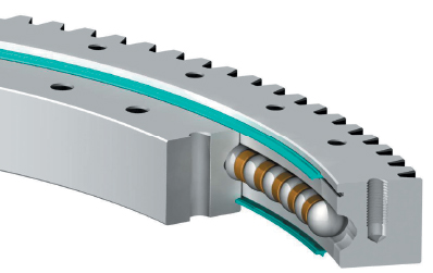
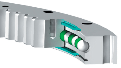
A crossed roller bearing, also called a crossed roller slideway, is effectively two sets of
bearings and races combined at right angles to each other. Cylindrical bearings or rollers mount along the length of a rail in a carriage. The rollers are held in place with a cage, preventing roller-to-roller contact, which increases friction and wear. Keeping rollers separated also eliminates any risk of them jamming.

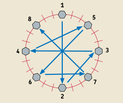
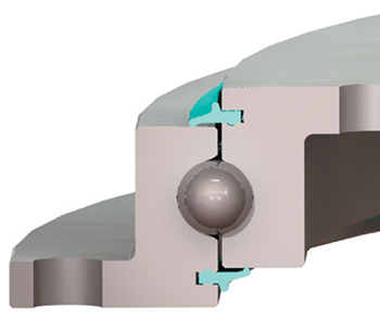
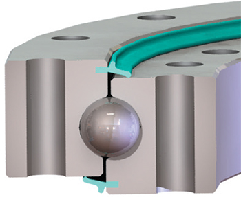
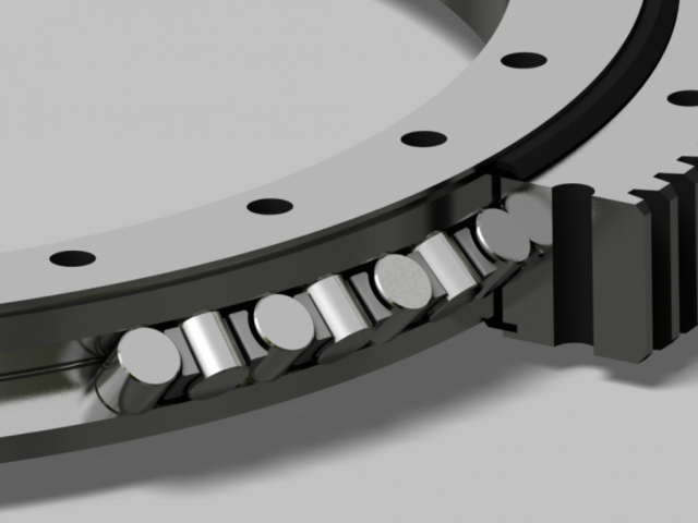
If you were to number the cylindrical rollers along the rail, the even ones would be mounted at 90° to the odd ones. In other words, the rollers alternate orientation. This lets the line of alternating rollers support loads from all directions, including high overturning moments, and because they do not recirculate like some ball bearings that line linear rails, all the rollers are constantly carrying the load except for pure radial loads, where, due to the criss-cross arrangement, only half of the rollers take loads at any one time.

The cylindrical rollers are mounted such that they create a protruding V-shape on the sliding rail. It fits into a corresponding V notch in the other rail that is likely carrying
the load.

crossed roller bearing

Rollers provide a full line of contact rather than just the point of contact a ball bearing provides. This gives crossed roller bearing a broader contact surface and the ability to carry heavier loads. It also increases the bearing’s rigidity so it deforms less and is thus more accurate. Plus, erosion is slower due to the crossed rollers’ consistency of contact between the carriage and the base.

There is a direct correlation between the combined contact area of all the rollers and load capacity: the greater the area, the higher the capacity. This lets bearing designers adjust load capacity by up to 250% by mounting rollers closer together. This permits more rollers to fit in the same space and increases the amount of weight per inch the bearing can carry.

Cross roller bearing do not use seals due to their construction, high precision, and low friction. Still, it is important to keep contaminants away from the rollers to prevent damage and wear. One way this is done, especially in IC manufacturing and lab equipment, is to install the machines using crossed roller bearings in clean, contamination-free environments.

It is also important to lubricate crossed roller bearings to get the most operational life out of them. A standard lubricant for them is lithium-soap-based #00 grease.

The configuration of crossed roller bearings gives designers all the benefits of a two-row bearing, including stability, in a single-row space.

Accuracy and Rails

Because of crossed rollers large contact area, they deform less than recirculating ball bearings and are stiffer, creating more precise and consistent motion. Because of this greater stiffness, crossed rollers provide consistently precise movement.

Crossed rollers are less forgiving of mounting surface inaccuracies than recirculating ball bearings due to their rigidity and the way they are designed. Ball bearings can handle imperfections on the order of five to ten 10 microns while crossed roller bearings need imperfections smaller than two microns for ultra precision.

Metal and Plastic Cages

One factor that determines how close rollers can be to each other is the cage (or retainer) holding them all in place, so its design is critical. An important factor in the design of the cage is whether it is made of metal or plastic.

Traditional metal cages use tabs on the carriage that fit into notches on the top and bottom of the rollers to keep them in place. This limits how closely a roller can be positioned between neighboring rollers, which then limits the crossed roller bearing’s load-carrying capacity.

But metal cages are less expensive and can be plain or stainless steel. Metal is more compatible with working in vacuums, including outer space, because plastic can out-gas and cause problems with electronics and optics. Stainless steel can also be beneficial in high-temperate applications and those requiring washdowns and where rust is unacceptable.

Plastic cages fit smoothly around each roller, exposing more of it to the load than a metal cage can. Plastic cages also pack rollers closer together so more rollers can be housed in the same rail. These two features mean the cage and rollers can be shorter while maintaining the same load capacity or the number of rollers can be increased within the same cage (compared to a metal version) and thus increase the load capacity. In fact, a plastic cage can yield a 30% to 58% increase in contact area compared to a metal cage. This increase translates to a 250% increase in load capacity.

Recent development in plastic cages has increased the number of design options available to engineers. They can now be shaped so that there’s even a larger contact area with less space between rollers. Plastic cages can also be thinner in critical areas.

Preventing Cage Creep

Metal and plastic cages both effectively float between the bearing’s rails and they both tend to drift away from the bearing’s longitudinal center over time, a phenomenon called cage creep. It happens when the linear bearing only makes partial strokes, especially when mounted vertically. The cage can restrict slide travel because once the cage has moved and the bearing makes its next full stroke, the off-center cage hits a rail endstop and is forced to center itself by skidding.

Hitting the endstop and skidding can damage the retainer, rollers, and slideway. And it could require a more powerful and expensive motor to offset the effects of creep. Cage creep also means the rollers are not rolling but slipping and causing metal-to-metal rubbing, which leads to wear.

If a crossed roller bearing has no defense against creep, technicians will often have to regularly readjust the linearmotion equipment and replace worn components. Creep
is particularly bad when applications require high levels of acceleration and deceleration, uneven preloading or load distribution, or vertical or inclined strokes.

Fortunately, there are anti-creep mechanisms that stop retainers from slipping by holding the rollers between the two V-grooved slideway rails. As a result, the rails can be used in any mounting orientation, and lower-momentum motors such as linear motors can be used to move the loads. Anti-creep devices also reduce downtime and the cost of maintenance.

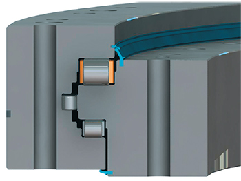
One anti-creep device, a rack-and-pinion mechanism, consists of external plastic gears and a metal gear inside the rail. Though effective, this approach is costly and makes it impossible to change out failed or worn bearing components.

Another approach to preventing creep uses rollers with spherical studs circling the middle of the roller’s round surface. As the rollers turn in the rail, they mesh with a row of holes or dimples machined down the exact center of the raceway tracks. This design, called Studroller at NB, prevents slipping regardless of the rail’s orientation or position. It creates smoother tracking motion than gear-based anti-creep mechanisms, so it is quieter and more accurate. Keeping the rollers aligned along the center of the rail also keeps all components aligned.

With the Studroller approach, the number of effective rollers increases by 20% to 55%. Contact area between rollers and the raceway surface jumps by 42% to 58%, which lets the load rating increase by 140% to 230%. This should lead to savings in cost and space required to mount the linear bearing.

Costs vary for crossed roller bearings with anti-creep devices depending on the complexity of the device whether the application must be custom designed and manufactured to accommodate them. The Studroller approach, being the simplest non-slip design, is priced the same as a standard crossed roller slideway, which is roughly half the cost of other anti-creep devices. And there are no redesign costs to replace a standard slideway.

Travel Lengths

For crossed roller bearings on linear sliderails, the rails’ lengths determine the length of the stroke or travel. The entire rail assembly must be twice as long as the stroke. That’s because both rails containing crossed roller bearings move in opposite directions. That means the whole assembly has to have room to move inside a space twice as long as the travel length. (Recirculating-ball bushings used for linear motion need shafts only as long as the required travel because the only moving component is the bushing.)

When the bearing uses plastic cages, stroke length can be longer on a given length of rail because the cage can be shorter for a given load.

So one limit on a crossed roller bearing’s travel is the space available in the application. As mentioned, with the rails moving in opposition to each other, the overall space required is twice the distance the load will travel. Endstops are components mounted on linear rails that physically limit travel length, stopping the rails from going farther.

Ratings and Life

The dynamic load ratings of crossed rolling bearings are based on the industry standard of 50 km of travel. In effect, it means that when you purchase several crossed bearings, 90% of them will last at least 50 km under normal operating conditions at its rated load. Using bearings with load ratings higher than an application requires usually lets the bearing last longer or withstand more demanding conditions.

It’s also important to select bearings with a margin of extra load capacity if accuracy is paramount. That’s because rollers and rails can deform when nearing their load limits, which can change the accuracy, sometimes permanently.


30 12 月, 2021

Slewing Bearing Clearance Measurement

Slewing Bearing Clearance Measurement:

The clearance of the slewing ring bearing is the maximum amount of movement in which one ferrule is fixed and the other rim is radially or axially.

The maximum amount of motion in the radial direction is called the radial clearance, and the maximum amount of motion in the axial direction is called the axial clearance.

The larger the radial clearance, the larger the axial clearance.

The slewing ring bearing clearance can be divided into the following three types:

Original clearance

The slewing bearing clearance in the free state before the bearing is installed. The slewing bearing original clearance is determined by the processing and assembly of the manufacturer.

Installation clearance

Also called the fit clearance is the clearance when the bearing and the shaft and the bearing housing are installed and not working. The installation clearance is smaller than the original clearance due to the interference installation, or the increase of the inner ring, or the reduction of the outer ring, or both.

Work clearance

When the bearing is in working condition, the inner ring temperature rises the most, the thermal expansion is maximum, and the bearing clearance is reduced. At the same time, due to the load, the rolling element and the raceway are elastically deformed, which makes the bearing clearance increase. Big. Whether the bearing working clearance is larger or smaller than the installation clearance depends on the combined effect of these two factors.

The clearance of the slewing ring bearing

Repeat the tilting clearance or axial reduction measurements under the same conditions at appropriate intervals, after first checking the bearing fastening bolts.

Double-row ball bearing slewing rings clearance:

Track diameter Ball diameter mm
up to mm 18 20 22 25 30 35 40 45 50 60 70
permissible increase in bearing clearance mm
1000 1.8 1.8 1.9 1.9 2 2.1 2.5 2.8
1250 1.9 1.9 2 2 2.1 2.2 2.6 2.9 3.4 3.6
1500 2 2.1 2.1 2.2 2.3 2.7 3 3.5 3.7
1750 2.2 2.2 2.3 2.4 2.8 3.1 3.6 3.8 4
2000 2.3 2.4 2.5 2.9 3.2 3.7 3.9 4.1
2250 2.5 2.6 3 3.3 3.8 4 4.2
2500 2.7 3.1 3.4 3.9 4.1 4.3
2750 2.8 3.2 3.5 4 4.2 4.4
3000 3.3 3.6 4.1 4.3 4.5
3250 3.4 3.7 4.2 4.4 4.6
3500 3.5 3.8 4.3 4.5 4.7
3750 3.6 3.9 4.4 4.6 4.8
4000 4 4.5 4.7 5
4500 4.2 4.7 4.9 5.2
5000 4.9 5.1 5.4
5500 5.1 5.3 5.5
6000 5.3 5.5 5.7
6500 5.7 5.9
7000 5.9 6.1
7500 6.3
8000 6.5

Single-row ball bearings (4-point bearings) double four-point contact bearings clearance:

Track diameter Ball diameter mm
up to mm 20 22 25 30 35 40 45 50 60 70
permissible increase in bearing clearance mm
1000 1.4 1.4 1.4 1.5 1.7 2 2.1 2.5
1250 1.5 1.5 1.6 1.7 2 2.2 2.6 2.7
1500 1.6 1.7 1.7 2 2.3 2.6 2.8
1750 1.7 1.8 2 2.3 2.7 2.9 3
2000 1.8 1.9 2 2.4 2.8 2.9 3.1
2250 2 2 2.5 2.9 3 3.2
2500 2 2 2.6 2.9 3.1 3.2
2750 2 2.6 3 3.2 3.3
3000 3 2.7 3.1 3.2 3.4
3250 3 2.8 3.2 3.3 3.5
3500 2.9 3.2 3.4 3.5
3750 3 3.3 3.5 3.6
4000 3.3 3.6 3.7
4500 3.5 3.8 3.9
5000 3.7 4 4.1
5500 3.9 4.2 4.3
6000 4.1 4.5 4.6
6500 4.6 4.7
7000 4.8 4.9
5.1
8000 5.3

Roller bearing slewing rings

The inspection method for the axial clearance of the slewing bearing crane is as follows:

1. Feeling method

Check the axial clearance of the rolling bearing with your fingers. This method is applied to the case where the shaft end is exposed. When the shaft end is closed or cannot be checked with a finger for other reasons, it can be checked whether the shaft is flexible or not.

2,slewing bearing clearance measurement method

measurement method

(1) Check with a feeler gauge. The method of operation is the same as that for checking the radial clearance with a feeler gauge, but the axial clearance should be

c=λ/(2sinβ)

Where c – axial clearance, mm;

Λ——the thickness of the feeler gauge, mm;

Β——bearing cone angle, (°).

(2) Check with a dial gauge. When the shaft is tilted with the crowbar to make the shaft at two extreme positions, the difference between the dial gauge readings is the axial clearance of the bearing.

However, the force applied to the crowbar should not be too large, otherwise the shell will be elastically deformed, and even if the deformation is small, the accuracy of the measured axial play is affected.

Certificate for Slewing Rings clearance Application: Location:
RE drawing-no.: RE-order-no.: Year of manufacture:
Date
Repeated measurements (every 12 months)
Measuring point Basic measurement 1 2 3 4 5 6 7
1 Boom
180offset
2 Boom
180offset
3 Boom
180offset
4 Boom
180offset
Grease-sample no Fe-magn. particle (%) 1
2
3
4
5
6
Greasing system Quantity/interval
Remarks

Given conclusive assessment of the crane slew ring ‘s condition, worn parts can be replaced in good time. In conjunction with optimum spare parts management, it is thus possible to avoid incidents of damage and lengthy downtimes.

  • Measurement of axial clearance for slewing bearing

First, the connecting screw of double half rings in slewing bearing should be tightened uniformly, to ensure the uniform fitting. Then place a datum level of the slewing bearing on the large platform, Three adjustable bearings are equidistantplaced from the neutral position of the lower two steps. Three measuring frame are equidistant placed on the end face of the upper slewing ring, put the pointer on the end face of the other slewing ring. When measuring, first push the three pointer to zero, adjust the bearing, make the slewing bearing face away from the large platform, the average of three pointer is the axial clearance of the slewing bearing.

  • Measurement of radial clearance for slewing bearing

Place the slewing bearing on the platform vertically, lift a slewing ring, Measure the clearance with the dead weight of the other slewing ring, Measure three point along the circumference of 120° and take the average .Other measurements are allowed.


28 12 月, 2021

Ball bearing slewing ring

Ball bearing slewing ring

Ball bearing slewing ring

Four-point contact ball bearings, double-row ball bearings, and double-row different diameter ball bearings are all typical point contacts. In the case of rotation, it can be understood as two concentric circles or four concentric circles. Ball bearing slewing ring, Actually The precision of processing is very demanding. The advantages are flexibility, fatigue resistance, convenient maintenance, quick installation, easy accuracy, long life, but the stability is slightly inferior to the cross roller and the three-row roller in the long run.

Ball bearings, mainly cross-roller bearings and three-row roller structures, Ball bearing slewing ring , line contact, in the state of motion, can be understood as surface contact, low speed and heavy load, high reliability and stability, but the speed and flexibility are obviously not as good as four points Contact the ball bearing.

The working conditions need to decide everything. In a general sense, four-point ball bearing can handle 80% of the working conditions. Special customization requires special design.

Rothe erde ball bearing slewing ring

1. The scientific name of the slewing bearing is the slewing ring. Before the slewing ring is selected, the operating environment and working conditions must be clarified.

2. Determine the maximum load of the slewing bearing. This load must include both the dynamic load and the static load applied to the slewing ring. The load applied to the ring should be converted into an equivalent load acting on the center of the slewing ring. Some things that must be noted:

· All external forces acting on the slewing ring and gear, not only the rated load or working load, but also the load that may occur suddenly when the equipment is stationary, such as the effect of strong wind on large buildings, etc.

· The load that may be generated in the case of overload or test

· Loads generated during installation and removal

· The weight of all structures supported by the slewing ring

· The sum of all possible loads. For example, a crane has various changes in load and working radius during normal use and overload test.

3. Multiply the calculated load by an appropriate safety factor.

4. Ball bearing slewing ring If you need a complete gear, you need to determine the load that the gear needs to bear. The calculation method is the same as that of the slewing bearing load, and all possible situations should be considered; to give a few examples, these situations include working, static, tilting, and overload testing. Another thing to pay attention to is the type of load in each case.

5. Ball bearing slewing ring After determining the installation layout, you need to consider the location of the large and small gears, the installation of the slewing ring and the fastening bolts, and the follow-up maintenance issues.

6. Ball bearing slewing ring Refer to the “Product Overview & Selection Guide” in the Wanda Slewing Ring Operation Manual to select the slewing ring series required for each location.

7. By comparing the previously calculated load and safety factor of the slewing ring with the load-bearing characteristic curve of the slewing ring, we can make a preliminary selection of the slewing ring. Be sure to ensure that all load combinations are below the load-bearing characteristic curve. In many cases, we now have several slewing bearings to choose from, all of which can meet the load requirements.

8. If possible, check the gear load capacity of the selected slewing ring.

9. Confirm that the arrangement of fixing bolts, fixing plates and joints are suitable for installation.

2. Selection elements of slewing bearings

Slewing bearings ,Ball bearing slewing ring  have unique load-bearing characteristics and are usually used in hoisting machinery, excavators, turrets, wind turbines, telescopes and tank turrets. Ball bearing slewing ring Through the improvement of machining methods and the upgrading of design, the slewing bearing at this stage can be used in smaller, more complex and more precise occasions.

The correct selection of slewing bearings depends on the requirements of load, stiffness, speed, size and rotational flexibility. Customers and manufacturers jointly select the design goals and the applicability of the bearing, which helps to optimize the performance of the system under the premise of the lowest cost and guaranteed trouble-free operation. Usually the load capacity is the decisive factor in choosing the bearing section size and diameter, but other parameters determine which bearing type is the best.

1. In general, double row four-point contact ball bearings are required for larger torque requirements.

2. Generally, roller bearings are required to increase rigidity.

3. The maximum load carrying capacity requires the use of cross rollers (two-row or three-row roller bearings)

For occasions requiring increased rigidity and load-bearing, large-size bearings are required, but for occasions with sensitivity requirements such as robots and manipulators, small-size bearings are required. The slewing bearing with a smaller inner diameter size makes the structure of the mounting component more compact and the total weight is reduced.

Ball bearing turntables and slewing rings

1. Ball bearing slewing ring can Dimensions, especially the stop, step size, relative position of the lubrication hole
2. Gear parameters, core key parameters
3. Quenching, channeling, and tooth roots
4. Gear center diameter
5. Mounting hole size, category, center diameter, wire hole size and type, key parameters
6. Original accuracy
7. Upgrade and promotion of installation conditions.

Ball bearing supported slewing ring

Design and selection and consider the core parameters of the large slewing bearing selection.
After fully considering the working conditions, the overall dimensions of the large bearing, installation dimensions, load capacity, speed, lubrication, protective measures, and design life can be selected so as to complement each other. .
1. First, determine the overall dimensions and installation dimensions of the large bearing.
This is the first issue to be considered. How many pots are there, and how many meters there are.
This determines the structure of the bearing.
2. Load, which needs to be calculated, including axial load, radial load, overturning moment, and impact load.
3. Rotation speed, the rotation speed of the slewing bearing is not high, more than 15Rpm, you need to consider the segmented cage, the overall cage.
4. Installation methods, such as horizontal installation, vertical installation, inclined installation, and multi-directional movement installation, the cage needs to be fully designed. 5. The lubrication method is convenient, fast and beneficial.
6. Design and utilization of ash guard
7. Accuracy standards.
8. Fully consider the advantages of each structure of the bearing. Four-point ball bearings are flexible and resistant to permanent fatigue. Double-row ball bearings have the above advantages while increasing the load. Crossed roller, anti-permanent deformation, strong rigidity, crossed tapered roller bearing, high precision, three-row roller bearing load is the highest under the same size.

What is ball bearing ring?

If the basic rotation is achieved, the load is not high, and the overturning moment is not large, the four-point ball bearing is sufficient.

If good rotation performance is required, and the load is more than 10 tons, double volleyball is the best choice.

To emphasize the rotation accuracy, consider the crossed roller bearing, of which the accuracy of the tapered roller bearing ,Ball bearing slewing ring is the most appropriate.

Selection and Application of Bearings for Slewing Bearings of Rotary Turntable

Three-row cylindrical rolle r bearings are the ultimate design goal, and corresponding changes are made in the size and material of the rollers to obtain different force enhancements.

Of course, the cost has also increased. According to different working conditions, the material of the bearing, the cage and the sealing system have targeted designs, divided into categories to facilitate the better and stronger operation of the equipment. This is where the strength of Luoyang Bearing.

What are the benefits of using ball bearing?

Slewing bearings ,Ball bearing slewing ring and double-row ball bearings have not been well-known for a long time.

First, many devices mostly use four-point contact ball bearings, but for double-row ball bearings, they ignore or adopt other structures. In fact, analyze the characteristics of double-row ball bearings as follows:

1. Realize good rotation performance

2. Anti-permanent fatigue

3. The load is relatively in the middle, that is, between the four-point kick and the three-row roller bearing, such as 15 to 40 tons cranes, crane cranes, cement pump trucks, etc.

4. Maintenance Convenient

5. Long service life.

Three-row roller bearings, considering the ultimate choice of heavy load and overturning moment, the technical characteristics are as follows:

1. Load more than 100 tons

2. Impact load, partial load and heavy load and complex force

3. Low speed

4. Lubrication system is relatively Complex 5. High cost

What are the ball bearings where are they used?

What are the general selection steps for slewing bearings , Ball bearing slewing ring?

1. The scientific name of slewing bearings is slewing ring.

Before slewing ring selection, the operating environment and working conditions must be clarified. 2. Determine the maximum load of the slewing bearing.

This load must include both the dynamic load and the static load applied to the slewing ring. The load applied to the ring should be converted into an equivalent load acting on the center of the slewing ring.

Some things to pay attention to: · All the external forces acting on the slewing ring and gears are not only the rated load or working load, but also the load that may occur suddenly when the equipment is stationary, such as the effect of strong wind on large buildings, etc. ·

In The load that may be generated in the case of overload or test, the load generated during installation and disassembly, the weight of all structures supported by the slewing ring, and the sum of all the possible loads.

For example, a crane has multiple changes in load and working radius during normal use and overload test.

3. Multiply the calculated load by an appropriate safety factor.

4. If you need a complete gear, you need to determine the load that the gear needs to bear. The calculation method is the same as that of the slewing bearing load, and all possible situations should be considered; to give a few examples, these situations include working, static, tilting, and overload testing. Another thing to pay attention to is the type of load in each case.

5. After determining the installation layout, you need to consider the location of the large and small gears, the installation of the slewing ring and the fastening bolts, and the follow-up maintenance issues.

6. Refer to the “Product Overview & Selection Guide” in the Wanda Slewing Ring Operation Manual to select the slewing ring series required for each location.

7. By comparing the previously calculated load and safety factor of the slewing ring with the load-bearing characteristic curve of the slewing ring, we can make a preliminary selection of the slewing ring.

Be sure to ensure that all load combinations are below the load-bearing characteristic curve. In many cases, we now have several slewing bearings to choose from, all of which can meet the load requirements.

8. If possible, check the gear load capacity of the selected slewing ring.

9. Confirm that the arrangement of fixing bolts, fixing plates and joints are suitable for installation.

2. Selection elements of turntable bearings Turntable bearings have unique load-bearing characteristics, and are usually used in hoisting machinery, excavators, turntables, wind generators, telescopes and tank turrets.

Through the improvement of machining methods and the upgrading of design, the slewing bearing at this stage can be used in smaller, more complex and more precise occasions.

The correct selection of slewing bearings depends on the requirements of load, stiffness, speed, size and rotational flexibility. Customers and manufacturers jointly select the design goals and the applicability of the bearing, which helps to optimize the performance of the system under the premise of the lowest cost and guaranteed trouble-free operation. Usually the load capacity is the decisive factor in choosing the bearing section size and diameter, but other parameters determine which bearing type is the best.

1. In general, double row four-point contact ball bearings are required for larger torque requirements.

2. Generally, roller bearings are required to increase rigidity.

3. The maximum load carrying capacity requires the use of crossed rollers (two-row or three-row roller bearings).

For occasions that require increased rigidity and load-bearing, large-size bearings are required, but for occasions with sensitivity requirements such as robots and operating devices, then Need to use small size bearings.

The slewing bearing with a smaller inner diameter size makes the structure of the mounting component more compact and the total weight is reduced. At the same time, for the occasions with higher speed and small structural deformation, it also reduces the moment of inertia.

How does ball bearings reduce friction?

1. Ball bearing slewing ring The accuracy of the transmission movement. The angle error of the gear in one revolution is required to be limited within a certain range, so that the gear pair transmission ratio changes little to ensure the accuracy of the transmission movement.

2. The smoothness of the transmission movement. Ball bearing slewing ring It is required that the rotation angle error within the range of one tooth of the gear is limited to a certain range, so that the instantaneous transmission ratio of the gear pair changes little, so as to ensure the smoothness of the transmission and reduce vibration, impact and noise.

3. Uniformity of load distribution. It is required that the working tooth surface in the transmission is in good contact to ensure uniform load distribution, otherwise it will cause the tooth surface stress concentration, premature wear and reduce the service life.

4. The rationality of the transmission backlash. It is required to leave a certain amount of backlash between the non-working tooth surfaces of the meshing gear teeth in order to store the lubricating oil, compensate for the elastic deformation and thermal deformation, and the manufacturing and installation errors of the gear.

What is the difference between ball bearing and roller bearing?

The accuracy and reliability of the three-row roller bearing crossed roller bearing and the four-point ball bearing are high? In fact, there is only more suitable, there is no difference between high and low.

From the technological point of view, Ball bearing slewing ring , three-row roller bearings are flat raceways.

Relatively speaking, the rotation accuracy is easier to achieve and meet. Taking the limit accuracy of 0.015 as an example, this end face runout is difficult to achieve, especially for large-diameter slewing bearings. . The advantage is that three-row roller bearings have the advantages of heavy-duty and high-precision bearings, and are widely used in shield machine bearings, ladle bearings and other high-precision turntables.

The cross-roller structure has special forces, uniform axial and radial forces, good rigidity, and deformation resistance. It can be said that it is leading in the field of bucket wheel bearings and stacker-reclaimer bearings.

1797/3230 and 1797/2635, as well as the smaller model 1797/2500, can dominate the entire field of bucket turbines. In power plants, bucket turbines and turntable bearings in thermal power plants are in the position of big names in the world. Generally speaking, it is appropriate to achieve good high rigidity and preload. Disadvantages, low speed limit, inflexibility, there will be ball crashing sound above 6RPM per minute.

The four-point ball slewing bearing has more than flexibility and controllable precision. The key is to cooperate with the integral cage, copper cage, steel cage, and PTFE cage. It is fully qualified for different equipment fields. It is definitely the top beam, the vanguard and Sniper. It is widely used in winding machine bearings, CT machine bearings, bottle blowing machine bearings, filling machine bearings and injection molding machine bearings. The characteristic is that it can adapt to high speed.

Do ball bearings need a cage?

Regardless of whether the slewing bearing is a ball bearing or a ball bearing,Ball bearing slewing ring  the spacer and the cage are indispensable.

Ball bearing slewing ring The role of the cage:
1. Reduce the friction between the rolling elements
2. Coordinate, distribute and guide the direction and trajectory of the rolling body
3. Standardize the force balance of rolling elements
4. On the basis of bearing forces, especially vertical, inclined and multi-directional forces, the application of integral cages and segmented cages is very necessary to prevent rolling bodies from squeezing during gravity and movement. Hard friction
5. Among high-speed bearings, the integral cage is the first factor in the design
6. In order to reduce friction, noise and wear, the application of copper cage, PTFE cage and PA66 cage is very critical.

Slewing ring Bearing – Port Crane Slewing Bearing

Ball bearing slewing ring

1. Material
2. Heat treatment
3. Clearance, runout, tooth jump
4. Comprehensive index, roughness, tooth grinding, depth of hardness layer, flaw detection
5. Reference life value of similar bearing operation


Ball bearing slewing ring

The quality inspection of slewing ring bearings can be divided into axial clearance and radial clearance according to different inspection methods. Radial clearance is the basis for the assembly of the inner group, outer ring and rolling element of the bearing, and the quality is carried out in accordance with national standards. Important items for testing.

From the perspective of bearing application, the clearance is an important indicator for testing. Whether the bearing can obtain a more satisfactory performance, which largely determines its radial clearance.

The specific testing is as follows: the high-frequency quenching hardness of the bearing surface should not be less than 55HRC, the depth of the hardened layer should not be less than 4mm, and the width of the soft belt should not be less than 50mm.Ball bearing slewing ring,  The entire processing process should be made according to customer needs.

Support bearings have certain requirements for quenching time and temperature for tempering. Under normal circumstances, they need to be quenched at a temperature of 200 degrees to ensure that all stresses disappear.

In addition, the most important thing is the grinding process. It is necessary to select a suitable grinding wheel to complete the grinding and strictly control the linear speed to avoid raceway burns.

Ball bearing slewing ring ,Then for fine grinding, you need to choose a 46° or 60° resin wheel for grinding. The amount of grinding cannot exceed that of rough grinding, and the finish must meet the requirements of the specified grade. For supporting bearings containing gears, after the grinding process, the gear hobbing process is required. The entire process is very strict, and the accuracy must exceed eight levels.


27 12 月, 2021

slew bearing design

Slew bearing design:

The slew bearing design, selection, customization, and reference factors and technical standards of slewing bearings for slewing bearings are theoretically obscure and difficult to operate. Even if the algorithm of the kimono specification, the actual working conditions are very different, it may not be reasonable.

The forces on the slewing bearing and the slewing bearing, such as axial load, radial load and overturning moment, are not necessarily indispensable technical factors, such as the force of the main bearing of the shield machine and the main bearing of the TBM.

Beyond thrust (which can reach 8000-12000 tons), because it is almost on the same forward horizontal surface, the overturning moment can be regarded as 0.

slew bearing design

Slewing ring bearing design:

1. The operating direction of the equipment is generally horizontal and axial rotation, tilt angle rotation, such as pelletizing machine, vertical direction is radial rotation, such as spiral CT machine, shield machine, TBM, etc.
2. Analysis of equipment working conditions: force distribution, axial, radial, overturning moment, thrust, eccentric load, impact force
3. The rotation speed of the device
4. The relationship between speed and heavy load, emphasizing equivalence or deviation
5. After selecting the structure of the slewing bearing, the economic factor is second
Next, as mentioned in this article, if you choose a four-point contact ball bearing, focus on the conditions of moderate speed and low heavy load, such as excavators, tower cranes, truck cranes, tire cranes and other equipment. Economic considerations are very obvious. If heavy load is considered, it is selected in three-row roller bearings, but the cost is appropriately high, and in terms of reliability and stability, there are more arrangements in terms of bearing material, heat treatment, machining accuracy, and process level.

Slewing ring bearing with external gear:

1. In order to improve the wear resistance of slewing bearings, tooth surface quenching is necessary, but considering the bearing load, you need to be cautious. 42CrMo material generally does not need quenching at all.
2. The rotation performance of the slewing bearing requires high levelness of the installation base surface and the installation base, otherwise, the deviation of the center of gravity will cause uneven force
3. The gear and pinion of the slewing bearing must mesh well
4. The main consideration for choosing 42CRMO instead of 50MN is that 42CrMo has a combination of flexibility and hardness, while 50MN has strong rigidity but fragility.
5. The slewing bearing and slewing bearing are frequently overhauled and the lubrication system is maintained to maintain normal lubricating oil, as a key measure for sealing protection.

Slew bearing tolerance:

First of all, it needs to be clear that whether the standard for slewing bearings is JB/T10471 or JB/T2300 for slewing bearings, in fact, to sum up, most of the applications of slewing bearings belong to the bulky field of heavy industry, and the accuracy of gear meshing Sexual requirements are not high, generally grade 10 teeth.

After the tooth surface is quenched, the accuracy level is lost to level 12. From the application, it does not affect the meshing. Therefore, emphasizing the high precision of the gear is a fuss and fault, and it is of no practical significance. It is just a waste of labor costs. .

Of course, when it comes to the accuracy of the slewing bearing, it is generally obtained through tooth grinding. Several key data of measuring gear are as follows.

Common normal length, common normal deviation, tooth jump, fixed string tooth height and tooth thickness, as for the tooth profile, tooth direction and tooth pitch, you need to use professional instruments to measure.

Regarding gear accuracy measurement, we are currently able to measure items such as common normal dimensional tolerance, common normal variation deviation, fixed chord tooth height and tooth thickness. For other gear accuracy requirements, such as tooth profile, tooth direction, tooth pitch, etc., currently unconditionally measured. In the case of tooth grinding, it is generally within a reasonable range.

Internal gear slewing bearing:

Internal gear bearing and external gear bearing: The gear accuracy ultimately determines the transmission accuracy of the slewing bearing rotation:
why would you say so? It should be known that the rotation accuracy of the slewing bearing includes end face runout, radial runout, and gear runout.However, when the slewing bearing rotates, the final output accuracy is concentrated on the gear accuracy, so the gear accuracy has the following parameters:

1. The number of teeth across the gear and the length of the common normal
2. The tooth jump of the gear, the highest point
3. The verticality of the gear
4. Tooth direction, tooth profile and tooth thickness
5. Quenching hardness of tooth surface
6. The hardness of the tooth surface
7. Gear shaping grade, according to gear hobbing grade 9-10, gear shaping grade 7-8
8. Finally, the roughness of the tooth surface is required. If the gear is shaped, it should be around Ra1.6, the hobbing should be around Ra3.2, and the grinding should be around Ra0.8.
9. The relationship between quenching and tempering hardness of gear and quenching hardness
10. The highest point of the final rotation accuracy of the gear should be the green paint standard.

Slew bearing design and selection:

1. Choose a good structure, this is the most basic working condition
2. Determine the material, because it affects the life and heat treatment process
3. Accuracy standards and key indicators, such as clearance, runout, rotation accuracy
4. The installation method directly determines the operation mode of the cage
5. Sealing protection
6. Lubrication method
7. Gear meshing
8. Anti-corrosion treatment
9. Utilization of ash shield
10. Matching size, stop, step size and positioning size.

The slewing bearing with gear ring has the function of transmitting power and simplifying the main machine mechanism. Among them, the internal gear slewing bearing has a compact structure, low contact stress during transmission, low wear, grease, easy to maintain lubrication for a long time, good dust-proof effect, and the protection requirements for the meshing part are relatively better than the meshing effect of external teeth.

With external gear structure slewing bearing, the method of tooth profile processing and detection is quick and convenient. High manufacturing precision. It is easy to obtain the highest precision of grinding teeth, and can maximize the use of supporting space. And the tooth profile has a large pitch circle diameter. A larger transmission ratio can be obtained.

At the same time, the circumferential force and torque of the pinion can also be reduced, thereby saving efficiency. Of course, in terms of manufacturing costs, most of the internal teeth are shaped gears, which requires long working hours, and most of the external teeth are gear hobbing, and the speed is fast. Therefore, internal gear bearings are generally more expensive than external gears.

Slewing ring bearing manufacturers:

Slew Bearing Design and selection are consider the core parameters of the large slewing bearing slewing ring selection. After fully considering the working conditions, the overall dimensions, installation dimensions, load capacity, speed, lubrication, protection measures, and slew bearing design life of the large bearing can be selected. .

1. First, determine the overall dimensions and installation dimensions of the large bearing. This is the first issue to be considered. How many pots are there, and how many meters there are. This determines the structure of the bearing.
2. Load, which needs to be calculated, including axial load, radial load, overturning moment, and impact load.
3. Rotation speed, the rotation speed of the slewing bearing is not high, more than 15Rpm, you need to consider the segmented cage, the overall cage.
4. Installation methods, such as horizontal installation, vertical installation, inclined installation, and multi-directional movement installation, the cage needs to be fully designed.
5. The lubrication method is convenient, fast and beneficial.
6. Design and utilization of ash guard
7. Accuracy standards.
8. Fully consider the advantages of each structure of the bearing. Four-point ball bearings are flexible and resistant to permanent fatigue. Double-row ball bearings have the above advantages while increasing the load. Crossed roller, anti-permanent deformation, strong rigidity, crossed tapered roller bearing, high precision, three-row roller bearing load is the highest under the same size.

Slewing ring bearing calculation:

Calculation method of static reference load Fa’ and M’
Single-row four-point contact ball
The selection and calculation of single-row four-point contact ball slewing ring are carried out according to the load angle of 45° and 60° respectively.
I, a=45° , a=60°
Fa’=(1.225•Fa+2.676•Fr)•fs Fa’=(Fa+5.046•Fr)•fs
M’=1.225•M•fs M’=M•fS
Then find the above two points on the graph, one of which is below the curve.
Single row cross roller type
Fa’=(Fa+2.05•Fr)•fs
M’=M•fs
Double-row reducing ball
For the calculation of the selection of the double-row reducing ball slewing ring, when Fr ≤ 10% Fa, Fr is ignored. When Fr>10%Fa, the pressure angle change in the raceway must be considered. Please contact us for its calculation.
Fa’=Fa•fs
M’=M•fs
Three-row roller type
When selecting the three-row roller slewing ring, only the effects of axial raceway load and overturning moment are calculated.
Fa’=Fa•fs
M’=M•fs


24 12 月, 2021

Slew Bearings,Slew Rings-LYMC Slewing Bearing Manufacturer

Slewing Bearing Assembly:

Slewing bearing is a kind of large bearing with special structure, which can bear the overall load such as axial load, radial load and overturning load.

It combines support, rotation, transmission, fixation, sealing, anticorrosion and other functions into one unit.

  • Inner and outer rings

Generally, slewing bearings consist of two rings, each ring contains  a precision raceway that is Induction quenched on the surface to a specified depth.

Each ring is forged from 50Mn or 42CrMo.

Different internal structures can be selected according to load capacity, including Single-row ball series、Double-row ball series、Double-line ball series 、Roller and ball combination series、Three-row roller series.

  • Rolling body

The precision rolling body can promote the relative rotation between the inner and outer rings.

Steel balls or rollers are often used as rolling body.

  • Isolation block

Spacer blocks usually made of nylon which are usually used to separate balls or rollers,

this prevent them from rubbing against each other directly .

Under special conditions , steel and copper holder can be used.

  • Mounting holes

The mounting holes are usually spaced along the surface of the inner and outer rings which along a uniform bolt circumference and equally spaced apart.

These holes can be through holes, threaded holes, blind holes, countersunk holes, etc. Sometimes, need to customize bolts with spacing requirements to meet a specific application.

  • Sealing strip

There are sealing strips on each side of the slewing ring bearing.

Its main function is to retain grease and prevent certain contaminants (such as dust and debris) from entering.

The seal is usually made of Nitrile Butadiene Rubber.

  • Plug

Drill a hole in the position of the non-gear ring or the outer ring of the non-gear bearing, and install the ball or roller into the slewing ring raceway.

The hole is plugged and fixed with a taper pin.

The unhardened clearance will be engraved with the word “S”, Namely: soft belt.

Slewing bearings are available in toothless or internal or external type.

Custom gear configurations are also available.

  • Greaser

The slewing bearing include at least one grease fitting

The number may increase with the diameter of the slewing bearings.

For gear bearings, the grease fitting is located on the inner or outer circle of the toothless ring.

  • The sign

The part number and serial number are engraved next to the plug of the slewing bearing.

How mounting can optimize slewing ring bearing performance

Mounting a slewing ring bearing in the proper structure is crucial to properly distributing bearing load and stress. Without an adequate structure, bearing performance is likely to suffer. So can the performance of the seals, pinions, gears, and bolts. Therefore, mounting should be considered very early in the design process.

Factors in bearing selection

The designer’s first task, of course, is to specify a size for the slewing bearing. The bearing manufacturer can recommend a size based on applied load and ideal mounting. In heavy equipment, for example, the primary task of the slewing bearing and its mounting structure is to handle an over-turning moment load. Also, a slewing ring bearing with integral gearing must be sized for adequate gear strength and pinion drive position. Another factor is how large the central opening in the bearing bore should be…this may have as much influence on bearing size as the maximum applied load.

Shrouding is another consideration. While most slewing bearings are sealed by their manufacturer, shrouding is usually advisable to help avoid seal damage and dirt and water influx. This is even more important if the application involves cleaning with high-pressure water. Figure 1 shows a typical arrangement.

Kaydon Bearings - mounting slewing ring bearings - typical mounting support shroudThis typical mounting support has a shroud to help keep out contamination.

Mounting structure integrity

The need for rigidity in the mounting structure cannot be over-emphasized. Experienced designers know they should avoid the shortcut of using a higher-capacity bearing to offset a flimsy mounting surface. If the bearing structure is not robust enough to uniformly transfer the increased loads to the bearing while uniformly supporting the bearing, more bearing capacity will not make up for it. The consequences may be clear immediately, as excess deflection or rotational resistance. Sometimes they show up later, as uneven gear wear or reduced performance due to concentrated load.

In many cases designers can follow the bearing manufacturer’s recommended thickness for a steel mounting plate. Such recommendations are based on the size of the rolling elements or ring sections. Thinner plates reinforced with gussets or channels are an alternative (Figure 2), so long as the reinforcement is uniform and has been verified with testing. The use of thin “riser plates” under the bearing should be avoided. They tend to provide rigid support only in localized areas, putting more stress on retaining bolts and rolling elements.

Kaydon Bearings - mounting slewing ring bearings - gussets near bearing mounting holes increase rigidityGussets added near bearing mounting holes increase rigidity.

Mounting structure deflection is another important factor. Finite Element Analysis (FEA) is a good way to evaluate this, but the results should be confirmed with testing (e.g., with a dial indicator), to be sure they are within the bearing manufacturer’s limits. Bearing distortion during maximum loading should be tested as well. Typical allowable mounting-structure deflections for four-point and eight-point bearings, as a function of bearing pitch and ball diameter, are shown in Figure 3. Consult the bearing manufacturer for alternate designs.

Kaydon Bearings - mounting slewing ring bearings - allowable deflection vs. raceway diameterAllowable deflection varies with ball size.

The mounting surface, like the bearing, should be manufactured to precise specifications. Slewing ring bearings mounted on out-of-flat surfaces can produce stress concentrations on the rolling elements even before external load is applied. The bearings are typically assembled at the factory with a small amount of internal clearance that compensates for a little out-of-flatness in the mounting surface.

Figure 4 shows typical allowable mounting surface out-of-flatness for four-point and eight-point bearings as a function of bearing pitch diameter and ball diameter. Consult the bearing manufacturer for alternate designs. Flatness outside the manufacturer’s specifications causes high frictional torque and reduces bearing life accordingly.

Kaydon Bearings - mounting slewing ring bearings - allowable flatness vs. raceway diameterOut-of-flatness, like distortion, should be gradual.

Fastening the bearing

The final step in the interface of bearing and structure is mounting the bearing. It should go without saying that the position tolerance of the mounting holes in the structure must correlate with the holes in the bearing rings and their position tolerance. Most through-holes in construction equipment are drilled marginally larger than the bolt, then true-positioned for proper alignment. Pilot diameters on the inner ring or the outer ring can be useful to locate the bearing and improve gear mesh accuracy.

A full circle of bolts on both the inner and outer rings is the best way to fasten a slewing bearing. Generally, the bolts should be SAE J429 Grade 8 or ISO 898-1, Class 10.9. The hole pattern in the bearing will be appropriate for its load ratings, assuming that the proper mounting and structural support guidelines are followed. However, since variations in mounting structures can affect bolt-load distribution significantly, designers should always verify that the bolts are adequate for their specific applications.

Non-uniform loads not only result in higher-than-desired bolt load, but can leave some areas of the bearing inadequately supported and restrained. This causes poor rolling element load distribution, increasing stress and hampering bearing performance.

All bolts should be tightened in accordance with the equipment designer’s instructions, to minimize the potential for premature wear, equipment damage, and even injury. Bolt tensioning should be done in three stages—30%, 80% and 100% of the equipment designer’s final design tension—using the “star” technique of cross-tightening bolts (see Figure 5). Check bolt tension regularly.

LYMC Bearings - mounting slewing ring bearings - cross-tightening bolts is a proven way to achieve recommended torqueCross-tightening bolts is a proven way to achieve recommended torque.

All bolts should be accurately tightened with calibrated equipment. Two common examples are a torque wrench or a hydraulic bolt tensioner to avoid over-torquing. The Hydrocam bolt tensioner from LYMC (Figure 6), for example, was designed specifically to install the bolts on slewing bearings. It assures uniform preload on all the bolts, optimizes yield strength, and is available in four different designs.

Kaydon Bearings - mounting slewing ring bearings - the Hydrocam hydraulic tensioner from SKF tightens bolts uniformly, without torqueThe Hydrocam hydraulic tensioner from SKF tightens bolts uniformly, without torque.

Bolted joints are made more resistant to loosening by increasing the “stretched” portion of the fastener; that is, the length of bolt from beneath the bolt or screw head to the first thread of engagement, as shown in the inner ring of Figure 7. Additional stretch length may be gained by tapping the mounting hole toward the bottom of the hole.

Kaydon Bearings - mounting slewing ring bearings - stretched bolts resist loosening during thermal distortion“Stretched” bolts resist loosening during thermal distortion.

Conclusion

Mounting structures play a key role in the performance of slewing ring bearings and should be considered early in the design process. A properly-sized bearing, mounted on a flat, rigid surface with the appropriate deflection and fastening strength, should readily achieve its full capacity and contribute to a successful application.


23 12 月, 2021

Slewing Ring Bearing

Slewing Ring Bearing

Slew rings have a few different names, including turntable bearings, slewing rings and slewing bearings. The purpose of slewing rings is to enable rotational motion between different components in a system (Ritbearing). That motion can be radial, axial or tilting.

2.How do I choose a slewing ring bearing?

Slewing ring bearing are typically used in applications where their ability to transmit relatively high loads is of primary importance. However, there are other potential application requirements that can have a significant impact in the selection of an appropriate slewing bearing, and they should be thoroughly considered during the selection process. These considerations include, among others, rotational speed, protection from contamination, accuracy, frictional resistance, and temperature range of the operating environment.

Kaydon Bearings - external gear slewing ring bearing

Steps for selecting a slewing bearing

This white paper outlines nine steps to follow in order to select the appropriate slewing bearing for a given application. Note that these guidelines apply to ‘normal slewing applications,’ which are defined as those that meet the following conditions:

  • Vertical axis of rotation
  • Compressive thrust and moment loading (see Figure 1)
  • Radial load less than 10% of the thrust load
  • Oscillation or intermittent rotation with occasional pitch line velocity (limited time for speeds to 500fpm for single row bearings and 300fpm for multi-row bearings)
  • Operating temperature within -20°F to +140°F (-29°C to +60°C)
  • Mounting surfaces reinforced and machined to bearing manufacturer’s criteria
  • Proper installation (see the Kaydon white paper ‘How mounting can optimize slewing bearing performance‘ for more information)
  • Periodic lubrication
  • Periodic confirmation of specified bolt tension

If yours is not a ‘normal application,’ consultation with your bearing supplier during the early stages of a project can help assure success.

Kaydon Bearings - slewing bearing selection, simplified - Compressive thrust and moment loading
Figure 1
Compressive thrust and moment loading

Step 1

Determine what is required of your application in terms of load, speed, accuracy, torque, environment, coatings, mounting arrangements, and lubrication. LYMC’s Specification Data Sheet lists the more common requirements; download the data sheet, use the online form .Early consultation with your bearing manufacturer will help assure selection of a bearing that provides the necessary features to meet your requirements.

Step 2

Determine all maximum bearing loads, being sure to include all dynamic and static loads imposed on the bearing.

Consider all applied forces to the bearing and gear—not only at rated and working loads, but also loads imposed during:

  • extreme weather conditions
  • impact or testing
  • assembly or disassembly
  • all other situations

These loads in turn must be simplified into the forces acting at the bearing’s center. See Figure 2.

Kaydon Bearings - slewing bearing selection, simplified - Resultant forces acting on or about a bearing
Figure 2
Resultant forces acting on or about a bearing

Step 3

Multiply the resultant bearing forces by the applicable service factor (SF). See Table 1 for the service factors of common applications, or use the LYMC Bearings slewing ring bearing selector tool.

Application service factors are based on a number of considerations. The primary considerations are the frequency of use at higher vs. normal loads and potential for extreme or impact loads. These factors may be superseded by customer specification, finite element analysis (FEA), or regulations by certifying authorities.

If the intended equipment and application do not appear in Table 1, select a comparable application for initial sizing. If unsure, consult with the bearing manufacturer.

Table 1—Service factors
Application Service factor (SF)
Aerial lift devices
Aerial baskets, platforms, ladders, etc. 1.00
Conveyors 1.00
Cranes
Mobile (loads limited by machine stability)
Normal construction duty (tire mounted) 1.00
Normal construction duty (crawler mounted) 1.10
Production duty such as scrap and ship yards 1.25
Forestry handling (logging) 1.50
Stacker cranes (must include dynamic forces as loads) 1.25
Pedestal or tower (loads not limited by machine stability)
Loads continually monitored by safe load device 1.25
Applications with risk of sudden impact load application 1.50
Excavators
Load limited by tipping 1.25
Load limited by hydraulic pressure relief 1.50
Index and turnstile tables* (include any shock loads for evaluation)
Occasional use with intermittent rotation 1.00
Frequent use with intermittent rotation 1.25
Frequent use with intermittent rotation and impact loads 1.50
Industrial manipulators and robots
Occasional service 1.00
Frequent service 1.25
Steering gear (must include dynamic and shock loads due to transit forces)
Pneumatic tires 1.25
Solid tires 1.50

* Excludes coilers/uncoilers

Step 4

If an integral gear is desired, determine the required gear capacity. As with bearing loads, consider all conditions that would generate potential gear loads. Examples include dynamic loads while working vs static loads; loads on incline; and overload testing. Consider also the duty cycle at each of these conditions.

Kaydon Bearings - internal gear slewing ring bearing

Step 5

Determine the preferred mounting arrangement, considering the pinion and gear location. Consider the requirements for installation and continued maintenance of the bearing and retaining bolts. Slewing bearings can be designed to suit a number of mounting arrangements.

See Figures 3 through 6 for examples of basic arrangements available from LYMC Bearings, which can be varied to suit the requirements of a specific application. The mounting structures shown are intended to be illustrative only.

Kaydon Bearings - slewing bearing selection, simplified - Pinion is attached to outer ring support and the upper structure is supported by the inner ring. A shroud over the outer seal and bolts prevents contamination under extreme conditions. Through bolt arrangement shown.
Figure 3
Pinion is attached to outer ring support and the upper structure is supported by the inner ring. A shroud over the outer seal and bolts prevents contamination under extreme conditions. Through bolt arrangement shown.

Kaydon Bearings - slewing bearing selection, simplified - Inner ring with through bolts supports the upper structure with pinion. An external shroud protects the gear teeth on the outer ring, supported by the lower structure with threaded bolts.
Figure 4
Inner ring with through bolts supports the upper structure with pinion. An external shroud protects the gear teeth on the outer ring, supported by the lower structure with threaded bolts.

Kaydon Bearings - slewing bearing selection, simplified - Pinion is attached to upper structure supported by outer ring. Location of gear on inner ring can provide protection from harsh external conditions. Threaded bolt arrangement shown.
Figure 5
Pinion is attached to upper structure supported by outer ring. Location of gear on inner ring can provide protection from harsh external conditions. Threaded bolt arrangement shown.

Kaydon Bearings - slewing bearing selection, simplified - Pinion is attached to lower structure supporting inner ring. Geared outer race supports upper structure. Through bolts used on inner ring and threaded bolts on outer ring.
Figure 6
Pinion is attached to lower structure supporting inner ring. Geared outer race supports upper structure. Through bolts used on inner ring and threaded bolts on outer ring.

Step 6

Review available bearing styles and cross-sections. Figure 7 features a few of the slewing bearing designs available from LYMC. LYMC’s slewing ring bearing Catalog 390 provides detailed information about the design features, sizes, and ratings of each bearing series.

Figure 7
Cross-sections of available Kaydon slewing bearings

Kaydon Bearings - slewing bearing selection, simplified - RK series slewing ring bearings
RK series

Kaydon Bearings - slewing bearing selection, simplified - MT series slewing ring bearings
MT series

Kaydon Bearings - slewing bearing selection, simplified - XR series slewing ring bearings
XR series

Kaydon Bearings - slewing bearing selection, simplified - TR series slewing ring bearings
TR series

Step 7

Make a preliminary selection by comparing the resultant operating bearing forces, including service factor (SF), to the bearing’s rating curve.

In order for a bearing to be appropriate for a given application, all required resultant force combinations should fall below the curve.

Assure all extreme load conditions fall below the bearing’s rating curve. If extreme load condition is static and only occurs several times during bearing’s service life do not include the service factor. Otherwise, include the service factor.

The maximum thrust rating of a bearing should exceed 3 times the maximum operating thrust force on the bearing, regardless of the moment force at that condition. This criteria is due to concern for rigidity of the supporting structure and ability to properly distribute the load around the bearing’s diameter. If the bearing desired does not meet this criteria, contact the bearing manufacturer for assistance.

Load curves for LYMC slewing ring bearings, such as the example in Figure 8, can be found using the LYMC slewing bearing selector or Catalog 390. Several bearings may meet the required load ratings.

Kaydon Bearings - slewing bearing selection, simplified - Maximum rating curves for several bearing types
Figure 8
Maximum rating curves for several bearing types

Step 8

Check the gear size, quality, and rating for suitability. View a sample gear rating chart, from LYMC Bearings.

The chart’s gear tooth rating (Fz) indicates the maximum allowable tangential gear tooth load for normal slewing ring bearing applications. Refer to page 21 of LYMC Catalog 390 for more details.

Step 9

Finally, confirm that the bearing you select meets all of your design requirements. The LYMC slewing bearing selector can help with obtaining preliminary data. Consult with bearing and other component manufacturers, and submit a completed specification data sheet to the bearing manufacturer to confirm proper bearing selection. Ultimately, the responsibility for choosing the appropriate bearing rests with the equipment designer.

Conclusion

Like all bearings, slewing ring bearings serve as a connection between two adjacent structures, allowing rotation and transmission of load between them. In addition, a slewing bearing typically includes features for simple and quick attachment to those adjacent structures, and a feature to facilitate the mechanical rotation of one ring and its adjoining structure relative to the other.

Slewing ring bearings have traditionally been thought of as large-diameter, heavy section, low-precision bearings. But today they are also readily available with bore sizes as small as 50 mm, making them ideal for robotics, radar pedestals, and other precision applications.

The use of a single large-diameter bearing makes it possible for wiring and plumbing to run through the bore of the bearing. This can simplify overall design, help protect components, and improve appearance.

Selecting the right slewing ring bearing is key. With attention to all relevant design requirements and with help from the bearing manufacturer, a slewing bearing can be specified that meets or exceeds all application requirements.


15 11 月, 2021

What is Slewing Bearing

Slewing ring is also called rotary bearing.

Some people also call it rotary bearing and slewing bearing.

English names are: sliding bearing, sliding ring bearing, turntable bearing and sliding ring. Slewing ring is widely used in real industry.

It is called “machine joint”. It is an important transmission component of machinery that needs to make relative rotary motion between two objects and bear axial force, radial force and overturning torque at the same time. With the rapid development of machinery industry, slewing ring has been widely used in shipbuilding equipment, engineering machinery, light industrial machinery, metallurgical machinery, medical machinery, industrial machinery and other industries.


What is the basic structure of slewing ring

Slewing drive is usually composed of worm, slewing bearing, housing, motor and other components.

Slewing Bearing
Slewing Bearing

As the core component adopts slewing ring, it can bear axial force, radial force and overturning moment at the same time. There are many forms, but the structural composition is basically the same.

From the left and right are (upper part):

  1. Outer ring (toothed or toothless)
  2. Sealing belt
  3. Rolling element (rolling ball or roller)
  4. Oil nozzle from the left and right are (lower part):
  • 1. Blocking
  • 2. Blocking pin
  • 3. Inner ring (toothed or toothless)
  • 4. Spacer or cage
  • 5. Mounting hole (screw hole or smooth hole)

What is the application of slewing ring in construction machinery

Slewing ring is widely used. Construction machinery is the first and most widely used place of slewing ring, such as earth moving machinery, excavator, disintegrator, stacker reclaimer, grader, roller, dynamic compactor, rock drilling machinery, roadheader, etc.

Others include concrete machinery: concrete pump truck, concrete mixing and distributing rod integrated machine, belt distributor, feeding machinery: disc feeder and sand mixer; Hoisting machinery: wheel crane, crawler crane, portal crane, tower crane, fork crane, crane, gantry crane;

Foundation treatment machinery: percussive reverse circulation drilling rig, rotary drilling rig, percussive rotary drilling rig, rotary drilling rig, reverse circulation rotary drilling rig, positive circulation rotary drilling rig, long screw engineering drilling rig, submersible engineering drilling rig, static pressure pile driver and pile driver;

Engineering vessel: dredger; Special vehicles: bridge inspection vehicle, fire truck, window cleaning machine, flat beam carrier, aerial work vehicle and self-propelled aerial work platform; Light industrial machinery: beverage machinery, bottle blowing machine, packaging machinery, filling machine, rotary bottle management machine, injection molding machine; Marine crane: floating crane.

What is the working mode of slewing ring

According to the actual use and design structure, there are different working modes. There are two basic working modes: 1. The inner ring is fixed for its support, and the outer ring rotates; 2. The outer ring is fixed for its supporting function, and the inner ring rotates.

Method for solving slewing ring noise

Control method of dust sound

If there are dust and other foreign matters in the rotary support, aperiodic vibration will occur.

The so-called dust sound, the magnitude of vibration and noise is uncertain, with or without.

Control method of dust noise: improve the cleaning method of slewing ring / rotary table bearing, and strictly clean the bearing, shaft, seat hole and matching parts before installation; Remove foreign matters in the lubricant; Improve the sealing of bearings; Avoid using plastic cages with impure materials or embedded foreign matters.

slewing bearing

slewing bearing catalogue

slewing bearing skf

slewing bearing assembly

slewing ring


Rotary table bearings have many structural types, such as toothless, outer toothed and inner toothed four point contact ball bearings, double row angular contact ball bearings, cross cylindrical roller bearings, cross tapered roller bearings and three row cylindrical roller combined bearings. Four point contact ball bearings have high static load capacity;

Cross cylindrical roller bearing has high dynamic load capacity; Through pre interference, the cross tapered roller bearing can make the bearing have greater support rigidity and higher rotation accuracy.

slewing bearing wear measurement

slewing bearing manufacturers

slewing bearing application

slewing bearing for sale

slewing bearing price

slewing bearing manufacturers in india

skf slewing bearing catalogue pdf

skf slewing bearing

rollix slewing bearing catalogue pdf

rotek slewing bearing

rothe erde slewing bearing

small slewing bearing

liebherr slewing bearing

rothe erde slewing bearing catalogue

ina slewing bearing

slewing ring bearing

slewing ring bearing manufacturers

slewing ring bearing calculation

slewing ring bearing price

slewing ring bearing manufacturers india


About us

Headquarters

Luoyang MC Bearing Technology Co.,Ltd (LYMC)
+86 13837949030

www.chinaslewingbearings.com/

[email protected]

LOCATIONS

We are everywhere


GET IN TOUCH

Follow our activity

LYMC bearings are the perfect alternative to the most common and well-known brands.